background image

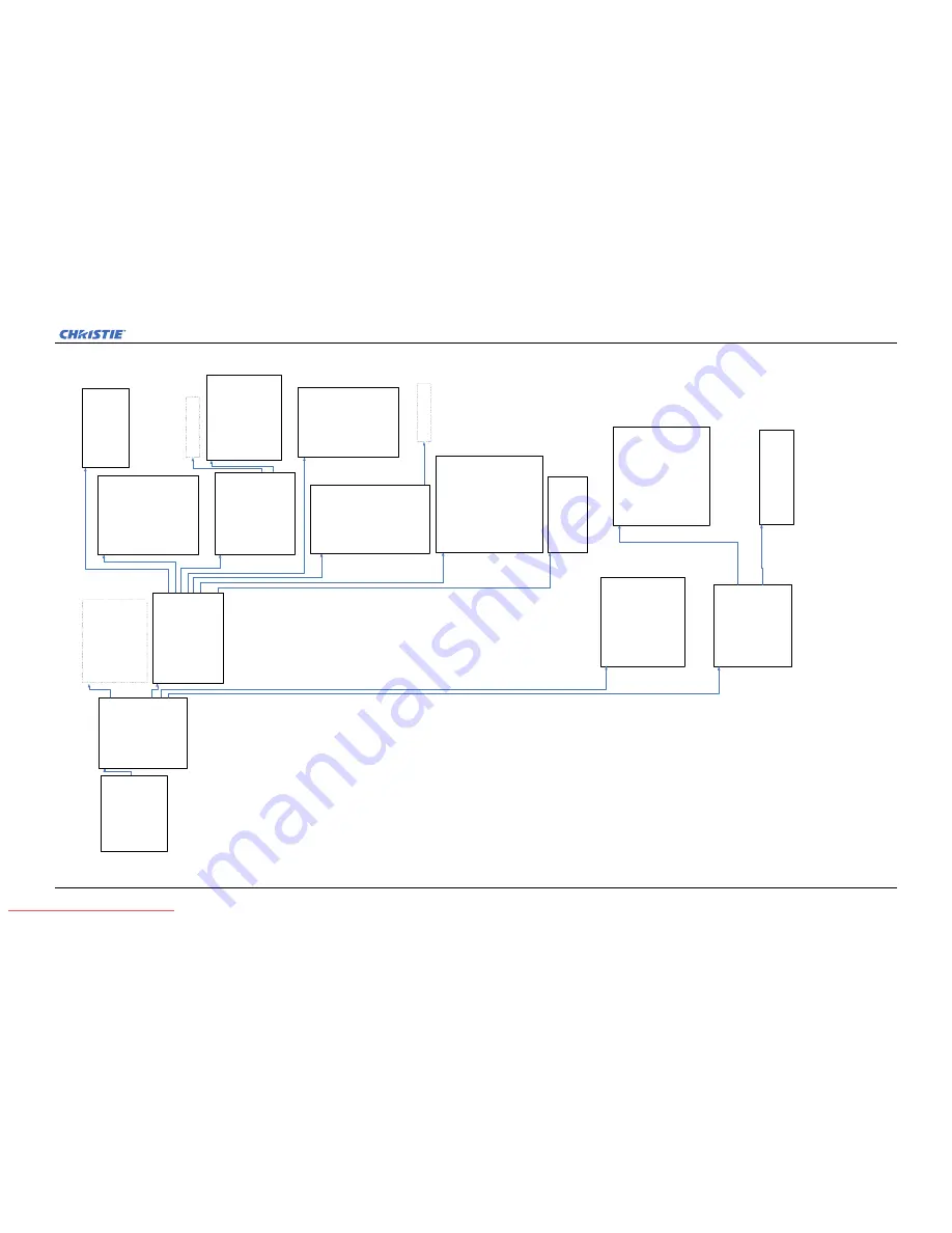
Appendix A: Menu Tree

Mirage J Series User Manual

A-5

020-100708-01 Rev.1 (11-2011)

Configuration

1.

Language

2.

Output

Options

3.

Lens

S

ettings

4.

Power

M

anagement

5.

Date

&

T

ime

6.

Menu

Preferences

7.

Communications

8.

Geometry

&

C

olor

9.

Diagnostics

&

C

alibration

10.

S

ervice

11.

O

ption

Card

S

ettings

12.

Reserved

Advanced

Main

Menu

continued

Color

A

djustments

by

X,Y

1.

Select

Color

Adjustment

2.

Color

Temperature

Valid

C

olor

Space

3.

Red

X

4.

Red

Y

5.

Green

X

6.

Green

Y

7.

Blue

X

8.

Blue

Y

9.

White

X

10.

W

hite

Y

11.

Reserved

12.

A

uto

C

olor

Enable

13.

C

olor

Enable

14.

C

opy

F

rom

Color

S

aturation

1.

Select

Color

Adjustment

2.

Red

P

art

of

Red

3.

Green

Part

of

Red

4.

Blue

Part

of

Red

5.

Green

Part

of

Green

6.

Red

P

art

of

Green

7.

Blue

Part

of

Green

8.

Blue

Part

of

Blue

9.

Red

P

art

of

Blue

10.

G

reen

Part

of

Blue

11.

R

ed

Part

of

White

12.

G

reen

Part

of

White

13.

B

lue

Part

of

White

14.

Reserved

15.

A

uto

C

olor

Enable

16.

C

olor

Enable

17.

C

opy

F

rom

18.

Lamp

Geometry

&

C

olor

1.

Test

Pattern

2.

Geometry

Correction

3.

Brightness

U

niformity

4.

Edge

Blending

5.

Color

Adjustments

b

y

X

,Y

6.

Color

Saturation

7.

Black

Level

Blending

8.

Default

C

olor

Adjustment

9.

Reserved

10.

T

iling

Setup

See

P

age

A

3

for

Lamp

Brightness

Uniformity

1.

Brightness

U

niformity

Enable

2.

Test

Pattern

3.

Coarse

Adjustment

4.

Top

Left

Corner

5.

Left

S

ide

6.

Bottom

Left

C

orner

7.

Top

Right

Corner

8.

Right

Side

9.

Bottom

Right

Corner

10.

C

enter

11.

Overall

G

ain

12.

Full

Screen

Eye-Motion

Filter

13.

Eye-Motion

Filter

14.

Reset

Brightness

U

niformity

Settings

Edge

Blending

1.

Edge

Blending

2.

Test

Pattern

3.

Left

B

lend

Width

4.

Right

Blend

W

idth

5.

Top

B

lend

Width

6.

Bottom

Blend

Width

7.

Lamp

8.

Show

Blending

Overlap

9.

Advanced

Edge

Blending

10.

F

ull

Screen

Eye-Motion

Filter

11.

Eye-Motion

Filter

12.

R

eset

Edge

Blending

Settings

See

P

age

A

3

for

Lamp

Black

Level

Blending

1.

Black

B

lend

Enable

2.

Test

Pattern

3.

Left

B

lend

Width

4.

Right

Blend

W

idth

5.

Top

B

lend

Width

6.

Bottom

Blend

Width

7.

Center

Brightness

8.

Left

Brightness

9.

Right

Brightness

10.

T

op

Brightness

11.

B

ottom

Brightness

12.

T

op

Left

B

rightness

13.

T

op

Right

Brightness

14.

B

ottom

Left

Brightness

15.

B

ottom

R

ight

Brightness

16.

R

eset

Black

Level

Blending

Settings

Advanced

Edge

Blending

1.

Enable

A

dvanced

Curve

2.

Left

B

lend

Shape

3.

Left

B

lend

Midpoint

4.

Right

Blend

S

hape

5.

Right

Blend

M

idpoint

6.

Top

B

lend

Shape

7.

Top

B

lend

Midpoint

8.

Bottom

Blend

Shape

9.

Bottom

Blend

Midpoint

10.

R

eset

Advanced

Edge

Blending

Settings

S

e

eP

a

g

eA

4f

o

r:

1.

Language

2.

Output

Options

3.

Lens

Settings

4.

Power

M

anagement

5.

Date

&

T

ime

6.

Menu

Preferences

7.

Communications

11.

O

ption

Card

S

ettings

Geometry

Correction

1.

Geometry

Correction

2.

Test

Pattern

3.

Adjust

Horizontal

Keystone

4.

Adjust

Vertical

Keystone

5.

Adjust

2D

Keystone

6.

Reset

K

eystone

settings

Tiling

S

etup

1.

Tiling

Setup

2.

Total

Rows

3.

Total

Columns

4.

Row

5.

Column

Diagnostics

&

C

alibration

1.

Test

Pattern

2.

Grey

Level

3.

Freeze

Image

4.

Color

Enable

5.

Input

Peak

Detector

6.

Input

Level

Detector

7.

Level

Detector

Threshold

8.

Aspect

R

atio

Overlay

9.

Test

Pattern

Color

Swap

10.

C

alibrate

L

iteLoc

Calibration

Status

11.

F

reeze

Image

During

Auto

Setup

Service

1.

Reserved

2.

Reserved

3.

Color

Primary

Settings

4.

Reserved

5.

Reserved

6.

Replace

B

ackplane

7.

Remote

Access

Level

8.

Restore

Factory

D

efaults

9.

Erase

Data

Files

10.

D

elete

A

ll

Real

Time

Events

11.

S

tatus

Requires

the

service

password

to

enter

this

menu

Color

P

rimary

Settings

1.

Red

X

2.

Red

Y

3.

Green

X

4.

Green

Y

5.

Blue

X

6.

Blue

Y

7.

White

X

8.

White

Y

9.

Reserved

10.

A

uto

C

olor

Enable

11.

C

olor

Enable

12.

R

eset

to

Factory

C

olor

Primaries?

13.

R

eserved

14.

R

eserved

Remote

Access

Level

1.

Remote

Access

Level

(Ethernet)

2.

Remote

Access

Level

(RS-232

IN)

3.

Remote

Access

Level

(RS-232

OUT)

4.

Remote

Access

Level

(RS-422)

Main

Menu

1.

Size

&

P

osition

2.

Image

S

ettings

3,

Channel

Setup

4.

Configuration

5.

Lamp

6.

Status

7.

Secondary

Input

&

S

witching

8.

Language

9.

Test

Pattern

Downloaded From projector-manual.com Christie Manuals

Содержание MIRAGE DS+8K-J

Страница 1: ...Mirage J Series U s e r M a n u a l 020 100708 01 Downloaded From projector manual com Christie Manuals...

Страница 2: ...Downloaded From projector manual com Christie Manuals...

Страница 3: ...Mirage J Series U s e r M a n u a l 020 100708 01 Downloaded From projector manual com Christie Manuals...

Страница 4: ...electrical and electronic equipment at their end of life should be disposed of separately from regular waste Please dispose of the product appropriately and according to local regulations In the Europ...

Страница 5: ...User Manual i 020 100708 01 Rev 1 11 2011 1 Introduction 1 1 Projector Overview 1 1 2 Operation 2 1 3D 2 1 A Menu Tree A 1 Mirage J Series Menu Tree A 1 B GPIO B 1 GPIO Port B 1 Downloaded From proje...

Страница 6: ...Downloaded From projector manual com Christie Manuals...

Страница 7: ...ess and high contrast ratios to produce flawless realistic three dimensional images for simulation virtual reality and other stereographic related applications This document applies to the following p...

Страница 8: ...Downloaded From projector manual com Christie Manuals...

Страница 9: ...aterial Hardware Christie 3D version of Mirage J Series projector Christie 3D Stereo Sync Cable required for 3D Mirage J Series models ensures minimum frame delay This General Purpose Input Output GPI...

Страница 10: ...projector setups Connecting Two Stereo 3D Sync Inputs Recommended for multiple sources Connect your video card s stereo 3D sync cable to either Input A or either Input B on the 3D Stereo Sync Cable Th...

Страница 11: ...asses Figure 1 Mirage J Series Typical Stereo 3D Configuration With Active Glasses Figure 2 Mirage J Series Typical Stereo 3D Configuration With Passive Glasses Appropriate Stereo 3D Source Use stereo...

Страница 12: ...d to prevent obvious ghosting of image content known as cross talk in stereo 3D applications and other more subtle color artifacts Such problems indicate that the eyes are detecting portions of the op...

Страница 13: ...me sequence Typically used for Blu ray 3D movies and 3D video gaming Triple Flash 3D 3D Content from a single 48Hz signal 24Hz per eye is displayed three times to provide you a 3D image to be viewed a...

Страница 14: ...gnal is used Set Frame Delay Delays the output signal timing relative to the input signal timing by a fraction of a frame and up to several frames The minimum latency can vary based on the amount of s...

Страница 15: ...tor in the array 8 Repeat the same procedure to all projectors except the last projector in the array Route the Sync output from the 3D dongle to the emitter NOTE For the last projector route the sync...

Страница 16: ...2 8 Mirage J Series User Manual 020 100708 01 Rev 1 11 2011 Section 3 Operation FIGURE 2 3 EXAMPLE OF 3D MULTIPLE DISPLAY SETUP Downloaded From projector manual com Christie Manuals...

Страница 17: ...Mirage J Series User Manual A 1 020 100708 01 Rev 1 11 2011 Appendix A Menu Tree A 1 Mirage J Series Menu Tree Downloaded From projector manual com Christie Manuals...

Страница 18: ...Downloaded From projector manual com Christie Manuals...

Страница 19: ...ber 2 Continue 3 Abort Change Lamp 1 New lamp Serial Number 2 Change Lamp Secondary Blanking Active Input Window 1 Top Blank 2 Bottom Blank 3 Left Blank 4 Right Blank Secondary Image Settings 1 Contra...

Страница 20: ...Input Card 3 Twin HDMI Input Card 4 Analog BNC Input Card Video Decoder Input card 1 Grouped Inputs Mode 2 Connector 1 Grounding 3 Connector 2 Grounding 4 Connector 3 Grounding 5 Connector 4 Groundin...

Страница 21: ...dth 4 Right Blend Width 5 Top Blend Width 6 Bottom Blend Width 7 Center Brightness 8 Left Brightness 9 Right Brightness 10 Top Brightness 11 Bottom Brightness 12 Top Left Brightness 13 Top Right Brigh...

Страница 22: ...Downloaded From projector manual com Christie Manuals...

Страница 23: ...here are 7 GPIO pins available on the 9pin D Sub GPIO connector which are configurable via RS 232 commands The other two pins are reserved for ground and power see table below for pin identification T...

Страница 24: ...ate or value of 0 will be read on an input pin if the circuit attached to the pin is open A high state or value of 1 will be read on an input pin if the circuit attached to the pin is shorted to groun...

Страница 25: ...Downloaded From projector manual com Christie Manuals...

Страница 26: ...chener ph 519 744 8005 United Kingdom ph 44 118 977 8000 France ph 33 0 1 41 21 00 36 Germany ph 49 2161 664540 Eastern Europe ph 36 0 1 47 48 100 Middle East ph 971 0 4 299 7575 Spain ph 34 91 633 99...

Отзывы: