background image

Printed circuit boards and sensors

HS Series 2K Service Manual—D13HD2-HS, D13WU2-HS, D16HD-HS, D16WU-HS, D20HD-HS, D20WU-HS 

94

020-001468-02 Rev. 1 (01-2020)
Copyright ©2020 Christie Digital Systems USA Inc. All rights reserved.

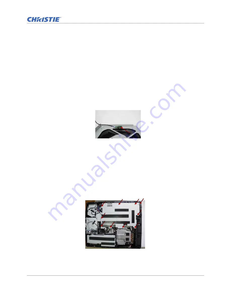
Removing the thermal sensor board

To remove the thermal sensor board, complete the following steps.

1. Remove the top cover.

See 

Removing the top cover

 on page 59.

2. Remove the main board top shielding.

See 

Replacing the main board

 on page 94.

3. On the main board, unplug the thermal-lvps connector. 

4. Remove the shielding


cover


on the left of the power supply.

See 

Replacing the DC 12V power supply

 on page 74.

5. Remove the one M2.6 screw with a Phillips Jewelers screwdriver securing the thermal sensor 

board.

6. Replace the thermal sensor board.

7. To re-install, follow these steps in reverse order.

Replacing the main board

To remove the main board, complete the following steps.

1. Remove the top cover.

See 

Removing the top cover

 on page 59.

2. To remove the main board top shielding, remove the ten screws with a Phillips #1 screwdriver.

Содержание D13HD2-HS

Страница 1: ...HS Series 2K D13HD2 HS D13WU2 HS D16HD HS D16WU HS D20HD HS D20WU HS Service Manual 020 001468 02 ...

Страница 2: ...e the product is designed for outdoor use problems or damage caused by use of the product outdoors unless such product is protected from precipitation or other adverse weather or environmental conditions and the ambient temperature is within the recommended ambient temperature set forth in the specifications for such product g Defects caused by normal wear and tear or otherwise due to normal aging...

Страница 3: ...es 10 Ordering parts 10 Replacing modules 10 Servicing live equipment 10 Safety and warning guidelines 11 AC power precautions 12 Installation safety and warning guidelines 12 Laser safety precautions 12 Light intensity hazard distance 13 Maintenance and cleaning 15 Guidelines for cleaning 15 Maintaining the cooling system 16 Ventilation 17 Power supplies 17 Power cord and attachments 17 Maintaini...

Страница 4: ...function test 32 Running a VGA port performance test 32 Running a HDMI port performance test 32 Running a DVI port performance test 33 Running a 3G SDI port performance test 33 Running a 3D SYNC out port performance test 33 Running a remote port performance test 34 Running a USB A port performance test 34 Completing a picture in picture picture by picture function test 35 Performing a network func...

Страница 5: ...Verify image performance 51 Verify image performance 52 Verify IR remote keypad operation 53 Verify the network connection 54 Parts and module replacement 55 Maintenance prerequisites 55 Tools required for service 55 Index of parts and modules 56 Projector covers and feet 59 Removing the top cover 59 Removing the rear cover 59 Removing the front cover 61 Removing the right side cover 62 Removing t...

Страница 6: ...he color wheel 84 Replacing the light engine 85 Replacing the DMD 88 Replacing the combiner and radiator module 89 Printed circuit boards and sensors 91 Replacing the LED board 91 Replacing the motor driver board 92 Replacing the rear IR sensor board 92 Replacing the front IR sensor boards 93 Removing the system thermal sensor board 93 Removing the thermal sensor board 94 Replacing the main board ...

Страница 7: ... HS Christie D20WU HS Christie D13HD2 HS Christie D13WU2 HS Site requirements To safely install and operate the projector the installation location must have restricted access for authorized personnel only and meet these minimum requirements Power connection The projector uses an AC power system that allows the projector to operate at full brightness with a power supply of 120 240 VAC or 200 240 V...

Страница 8: ...on the rear of the projector ID Part name Description 1 Front IR sensors Receives signals from the IR remote keypad Keep the signal path to the sensor unobstructed for uninterrupted communication with the projector 2 Projection lens Allows automated lens control and adjustment vertical and horizontal offsets zoom and focus 3 Adjustable feet Raises or lowers the feet to level the projector ID Part ...

Страница 9: ...these vents unobstructed to prevent the projector from overheating ID Part name Description 1 Built in keypad Controls the projector 2 AC input Connects to the supplied power adapter 3 Power button Powers the projector on or off 4 Kensington lock Secures the projector to counter tops tables and so on 5 Fuse FUSE T15A 250V 6 Cooling air vents intake Provides cooling to the projector Keep these vent...

Страница 10: ...ts Failure to do so may result in unsafe operation Servicing live equipment Only Christie qualified technicians who are knowledgeable about the hazards associated with hazardous voltage ultraviolet exposure and high temperatures are authorized to assemble install and service Christie equipment To make sure you remain safe when servicing energized live Christie equipment Locate the main AC power sh...

Страница 11: ...led within a restricted access location not accessible by the general public Only personnel who are trained on the precautions for the restricted access location can be granted entry to the area FIRE HAZARD Keep hands clothes and all combustible material away from the concentrated light beam of the projector TRIP OR FIRE HAZARD Position all cables where they cannot contact hot surfaces be pulled b...

Страница 12: ...mmended by Christie FIRE AND SHOCK HAZARD Do not attempt operation unless the power cord power socket and power plug meet the appropriate local rating standards SHOCK HAZARD Do not attempt operation if the AC supply is not within the specified voltage and current as specified on the license label SHOCK HAZARD The AC power cord must be inserted into an outlet with grounding SHOCK HAZARD Disconnect ...

Страница 13: ...T TEMPORARY BLINDNESS HAZARD No direct exposure to the beam must be permitted LASER RADIATION HAZARD This projector has a built in Class 4 laser module Never attempt to disassemble or modify the laser module Possibly hazardous optical radiation emitted from this product Only Christie qualified technicians who are knowledgeable about the hazards associated with laser use high voltage and high tempe...

Страница 14: ...ning Risk Group 3 laser illuminated projectors must meet the following conditions Installed by Christie or by Christie authorized and trained installers Refer to the Laser Illuminated Projector Class 1 Risk Group 3 Installation training Course code CF LIPI 01 on the http www christieuniversity com site Performed according to instructions provided by Christie Projection lens Part number Hazard dist...

Страница 15: ...nts Maintenance and cleaning Maintain the cleanliness of all internal components during any service procedure All of the projector optics must remain free of contaminants to perform at the level specified Even a small amount of dust or a fingerprint may degrade the image or cause a noticeable reduction of brightness Always power down and disconnect disengage all power sources to the projector befo...

Страница 16: ...he panels Blow off particles with clean dry deionized air Fan Check for dust build up on blades Inspect harness connection for proper seating Never touch or blow on the fan blade Blow off particles with clean dry deionized air Projection lens To avoid the risk of scratching the lens only clean the lenses if absolutely necessary A small amount of dust on the lenses has little effect on picture qual...

Страница 17: ... by increasing the risk of damage to delicate coatings and surfaces Warning If not avoided the following may result in equipment or property damage FIRE AND SHOCK HAZARD Use only the attachments accessories tools and replacement parts specified by Christie SHOCK HAZARD Do not attempt operation if the AC supply is not within the specified voltage and current as specified on the license label SHOCK ...

Страница 18: ...as minimal effect on image quality To avoid the risk of scratching the lens clean only if absolutely necessary 1 Brush most of the dust away with a camel hair brush and or blow dust away with a dust free blower 2 Fold a microfiber cloth smooth and gently wipe dust particles from the lens Wipe evenly with the smooth portion of the cloth that has no folds or creases Do not apply pressure with your f...

Страница 19: ...sted below PC or laptop with WUXGA 1080p resolution DVD player with Multi system equipped Component S Video Composite and HDMI HDTV Source 480P 720P 1080P Quantum Data 802B or CHROMA2327 Color Video Signal and Pattern Generator Chroma meter CL200 HD BaseT extender CH 506TX VGA cable power cord component cable audio cable HDMI cable RJ45 cable and RS232 cable Phillips 1 screwdriver Flathead 3 16 X ...

Страница 20: ...rase all end user settings and restore the default on screen display setting 1 Enter Service mode See Entering Service mode on page 19 2 Select Factory Reset Test inspection Complete the required update according to the table below for part replacements indicated by X Update Parts replaced Main board I O board Lan board Color wheel Firmware DMD board DMD Light engine Combiner Firmware version upda...

Страница 21: ... or press ENTER to input the values of pixel phase 2 Select Menu Size Position Horz Position or Vert Position 3 Adjust the slider by arrow keys or press ENTER to input the values of moving pixels 4 After inputting the value press ENTER to apply Adjusting color performance Use the HDTV 408p 720p 1080p source to complete the test The color does not turn purple and blue Warning If not avoided the fol...

Страница 22: ...ress Menu 4 To execute the light sensor calibration select 4 Light source 5 Light sensor Yes After the calibration has completed successfully the display shows Light sensor calibration has been done 5 If the display shows Light sensor calibration fail adjust the ABC adjustment gear using a M4 socket driver as indicated by the arrow 6 Run the light sensor calibration again until the display shows L...

Страница 23: ...ration Lens Setting 3 Select Lens Calibration 4 Press Enter Analog digital convert calibration If the color appears abnormal after upgrading the scalar firmware perform an analog digital convert ADC calibration Warning If not avoided the following could result in death or serious injury Do not stare into beam when the projector is on The bright light may result in permanent eye damage ID Part name...

Страница 24: ...rom Doing to Done Performing a video calibration To perform the video calibration complete the steps below 1 On the IR remote keypad press Menu and select Size Position Size Presets Full Size ID Part name Description 1 Test equipment Video generator output level 700 mv 2 Test signal Timing 800 x 600 60Hz 3 Test pattern 16 Gray 4 Inspection item Check if the ADC calibration status has changed from ...

Страница 25: ...rned 2 Remove the top cover See Removing the top cover on page 59 3 To power on with the top cover removed firmly hold the interlock switch on the left side cover 4 Project an image of 100 inch in a dark environment 2 Lux 5 Enter Service mode See Entering Service mode on page 19 6 Click Test Pattern select the White Screen test pattern Warning If not avoided the following could result in death or ...

Страница 26: ...he ROD until the yellow or blue image artifacts disappear 11 If the artifacts do not disappear adjust screw Z followed by the X and Y screws 12 To fix the screws use Loctite 222 or green glue BONBOND LOCK BB 2100 13 Update back the normal firmware for use Adjusting the focus If the project image appears fuzzy with the unbalance over 50 cm perform adjusting the focus Warning If not avoided the foll...

Страница 27: ... pattern 2 Adjust the lens zoom to its widest position 3 Adjust the focus to make the picture as fuzzy as possible 4 Measure and confirm the minimum imaging values are differ less than 3 cm from the lens specification values If the value does not meet the lens specification within 3 cm adjust the three set screws with a M4 Allen key If the value does meet the lens specification perform a bore sigh...

Страница 28: ...ent complete the following steps 1 Project a focus test pattern 2 To optimize the focus of position 1 on the screen press the FOCUS or key 3 Once position 1 is in focus check position 2 If position 2 is not in focus use the FOCUS or key to bring position 2 into focus on the screen If pressing the FOCUS key results in position 2 coming into focus turn the set screw A clockwise Items Description A B...

Страница 29: ... the screen 7 If the projector is still not in focus reset the set screw position d Turn the set screws counterclockwise until tight e Turn the set screws 1 5 turns in the clockwise direction back to their factory default setting f Check that the alignment of the set screws matches what is shown in the image above Adjusting the phosphor index After replacing main board combiner and upgrading firmw...

Страница 30: ...downwards until blue does not appear smooth d Record the b index value e Set the index value to a b 2 Adjusting the color index After replacing main board combiner color wheel and upgrading firmware proceed with the color index adjustment Warning If not avoided the following could result in death or serious injury Do not look into the projector lens when the laser is on The bright light may result...

Страница 31: ...9 3 Select Wheel Index 2x or select Wheel Index 3x 4 Select Filter Index 5 Set up for the color index value Only confirm the red and bule color level as the other color levels are not taken into account a Adjust the index upwards until blue does not appear smooth b Record the a index value c Adjust the index downwards until blue does not appear smooth d Record the b index value e Set the index val...

Страница 32: ...Switch the signal source to VGA The image of video generator should be projected Running a HDMI port performance test To verify the HDMI port functionality conduct a performance test on the HDMI port To perform the HDMI port performance test complete the following steps 1 Connect the projector and DVD player using a HDMI cable 2 Switch the signal source to HDMI The image of DVD player is projected...

Страница 33: ...following steps 1 Connect the projector and DVD player using a toaxil cable 2 Switch the signal source to 3G SDI The image of DVD player generator is projected Running a 3D SYNC out port performance test To verify the 3D SYNC out port functionality conduct a performance test on the 3D SYNC out port ID Part name Description 1 Test equipment Video generator 2 Test signal General 1 1024 x 768 60Hz 3 ...

Страница 34: ...R remote press Menu The image of on screen display menu is projected Running a USB A port performance test To verify the USB type A port functionality conduct a performance test on the USB type A port 3 Inspection item 3D SYNC port performance test 4 Inspection distance 1 8 to 2 2 m 5 Criteria No abnormal color performance line distortion or noise exist on the screen ID Part name Description 1 Tes...

Страница 35: ...ote keypad press Menu Input Switching PIP PIP PBP Enable 2 Set PIP PBP Enable to On 3 Ensure each item is functioning normally Performing a network function test on the network port The following browsers are supported for this test Internet Explorer IE8 for WinXP IE9 or higher for Win7 and IE11 for Win8 1 or Win10 is required Chrome Version 49 or higher is required Firefox Version 46 or higher is...

Страница 36: ...a RJ45 cable b Use Internet Explorer to navigate to http 192 168 0 100 c For the Access type select Administrator d Enter the password admin e Click Login Performing a network function test on HDBaseT port The following browsers are supported for this test Internet Explorer IE8 for WinXP IE9 or higher for Win7 and IE11 for Win8 1 or Win10 is required Chrome Version 49 or higher is required Firefox...

Страница 37: ...unction test on HDBaseT port To perform the RS232 and video function test complete the following steps 1 Connect the CH 506TX projector and PC as shown in step 5 2 Switch the signal source to HDBaseT 3 On the IR remote keypad press the Menu button and select Configuration Communica tions Serial port HDBaseT 4 Set the PC Baud Rate to 115200 5 Input the RS232 command SYS The projector returns the fo...

Страница 38: ...Horizontal and Vertical Size controls 4 Display data channel The purpose of the DDC test is to verify the DDC DDC1 DDC2B operation of the projector and to verify Plug Play function 5 Acoustic High pitch sounds from cooling fans and color wheel are unacceptable ID Check item Check point 1 Labels Missing letters and blurry print are unacceptable 2 Exterior surfaces and covers Dirt scrapes and uneven...

Страница 39: ...ade procedure is the same for D16WU HS D16HD HS D20WU HS D20HD HS D13WU HS and D13HD2 HS D16WU HS is used as an example Minimum system requirements Hardware Projector Power cord provided with the projector and appropriately rated for your region RJ45 cable CAT 5e or wireless dongle PC laptop mobile or tablet installed with a web browser Software Firmware upgrade program Web browser Internet Explor...

Страница 40: ...ample if the projector IP address is 192 168 000 100 set the computer IP address to 192 168 000 xxx where xxx is not 100 4 Open a web browser and type the projector address in the browser address bar 5 In the Username field type the username 6 In the Password field type the password 7 Click Login Upgrading the firmware To complete the firmware upgrade process complete the following steps 1 From th...

Страница 41: ...normally Blue flashing Projector is cooling down Blue solid Projector is in standby mode Yellow flashing A problem exists with the projector that does not cause it to shut down Examples of warnings include filter needs changing one of the pumps is damaged or a fan is operating at full speed due to over temperature of laser diode LD driver Yellow solid The end user is turning off the projector whil...

Страница 42: ...fter an error threshold being reached Error threshold for liquid cooling module Learn the error threshold in RPM for the liquid cooling components The projector shutdowns in 30 seconds after the error threshold being reached LED Status Projector State Off Projector is on and an image is displayed Shutter is open Magenta solid Projector is on and the image is blank Shutter is closed Temperature sen...

Страница 43: ...al Systems USA Inc All rights reserved Warning thresholds for fans The projector shutdowns in 30 seconds after a warning threshold being reached All fan warnings are set to 75 of their normal operating speeds in RPM at full power mode Fan Warning RPM Fan 1 2520 Fan 2 2520 Fan 3 2520 Fan 4 2520 Fan 5 2520 Fan 6 2520 Fan 7 2520 Fan 8 1960 Fan 9 2870 Fan 10 2870 ...

Страница 44: ...er to verify power functionality Is the image quality good Refer to verify image performance No Is the IR remote keypad working Refer to verify the IR remote keypad operation No No fault found Yes No End Is the network connection functioning Refer to verify the network connection No Yes Yes Is the correct PIN code Refer to verify PIN protection section Is the power button backlit Refer to verify p...

Страница 45: ...rd connected securely at the projector and at the power source Is the power source providing AC voltage Yes No Properly connect the power cord at The projector and AC power source Supply AC voltage 100 120V or 200 240V Is the interlock switch closed Yes Ensure the interlock switch is in the closed position Measure the JLVPS0 pin5 6 on the main board is output 5V Yes Replace the LVPS Replace the ma...

Страница 46: ...PS1 on the main board pins 1 11 is output 12V Replace the LVPS Measure the voltages of JLD1 JLD2 JRLD0 pin 2 on the main board is output 3 3V Replace the main board Replace the LD driver Yes No No No Replace the LVPS 5V 0V 0V 0V Yes 12V Ensure all connectors are connected proprely No Yes 3 3V Yes Are the lasers off and the status LED light blue in color Measure the JCW522 on the main board pins 2 ...

Страница 47: ...locked and that the operating temperature is less than 40oC Measure the DC voltage on JFAN1 JAN8 pin1 on the main boar is output 12V 10 Replace the main board Yes Is the projector functioning as expected and is the status LED green Replace the thermal switch No Measure the DC voltage on JFAN1 JAN8 pin3 on the main board is output 3 3V 10 No Replace the corresponding fan or blower No Is the project...

Страница 48: ...erved Verify PIN protection Normal operation Is the PIN protection turned on Show Enter PIN dialog Box on the screen Yes Is the PIN correct Yes Start No Turn off the unit then Hold the power Button and press the Enter button at the same time PIN will be reset to default Default PIN Sequentially press these keys 1 2 3 4 5 Enter into main menu to turn PIN protection on No Yes Enter the PIN code ...

Страница 49: ...there bright dots on the screen Replace the DMD Module Is the screen displaying white Replace the DMD board Replace the main board Ensure that the signal cable and signal source are working Does PC image show on the screen Replace the main board Yes Yes No Yes No No Yes 1 2 No Yes No Is the image flickering Yes Yes Check connection between main board and light engine Is the image flickering No Rep...

Страница 50: ...l source are working Follow the color wheel and phosphor wheel index adjust procedure Does the color appear normal Yes No No 1 2 1 3 Replace the main board Does the color appear normal Replace the color wheel module No No Does the Video image show on the screen Ensure that the signal cable and signal source are working Does the Video image show on the screen Replace the main board No No Yes Does V...

Страница 51: ...e DMD module and light engine module Ensure there is no dust on the socket and LVDS bus to DMD gold finger and this need to be done in a clean room Is there noise in the image Check the signal cable and signal source connection and functionality Adjust the pixel phase by selecting 1 Size Position 2 Pixel phase to adjust phase in the Menu Has the Image noise been resolved Replace the main board Yes...

Страница 52: ... 1 4 Is the lens shift working correctly Is the horizontal lens shift working correctly Replace the horizontal lens motor Is the vertical lens shift working correctly Replace the vertical lens motor Replace the light engine Yes Yes Replace the light engine Yes Is the image uniformity good No Is the image uniformity good No Yes Yes Is the horizontal lens shift working correctly Is the vertical lens...

Страница 53: ...ad troubleshooting Replace the battery of remote controller Is the unit powered on Is the unit power on Check the IR board connections in the remote Does the OSD menu show up on screen Press the menu button on the IR remote keypad No No No Fault Found Yes Plug in signal cable and power cord then press the power button on the remote Are the other functions on the IR remote keypad working End Yes Re...

Страница 54: ...I O panel RJ45 connector Is the RJ45 Connector LED green Are the Network settings of the unit correct Is the Network functioning correctly No Fault Found End Is the Internet source on the PC working Replace the Lan cable Use an alternate PC Change the Network setting Refer the Chapter about Network setting Is the RJ45 connector LED green Replace the Lan board Replace the main board Replace the mai...

Страница 55: ...cing the projector perform the following tasks Always power down and disengage all power sources to the projector prior to servicing Follow all service safety guidelines For detailed breakdown of serviceable modules see Index of parts and modules Tools required for service The tools required for service are listed below Phillips 1 screwdriver with magnetic tip Phillips 1 elbow screwdriver with mag...

Страница 56: ...X Top cover interlock switch 003 006617 XX Filter switch 003 005619 XX AC inlet switch 003 006618 XX 15A AC inlet 003 006616 XX DC 12V power supply 003 005645 XX Thermal switch 003 005622 XX Main power supply D16HD HS D16WU HS 003 006633 XX Main power supply D20HD HS D20WU HS 003 006632 XX Main power supply D13HD2 HS D13WU2 HS 003 006939 XX Optics Color wheel 003 006625 XX DMD chip WU 003 005935 X...

Страница 57: ...X Main printed circuit board D16HD HS 003 006630 XX Main printed circuit board D16WU HS 003 006631 XX Main printed circuit board D13HD2 HS 003 006944 XX Main printed circuit board D13WU2 HS 003 006943 XX Mechanical Front cover black 003 006626 XX Nameplate 003 006619 XX Cable cover 003 005631 XX Bottom cover black 003 005632 XX Keypad cover black 003 005628 XX Keypad button black 003 005281 XX Rea...

Страница 58: ...ower cord JP 003 006601 XX Power cord JP US 003 005849 XX Power cord TW 003 006721 XX Power cord US 15A 003 005659 XX Power cord US 20A 003 005658 XX Accessories Remote control 003 005238 XX Optional lens TR 1 2 1 5 140 109101 XX STD lens TR 1 5 2 0 140 110103 XX Optional lens TR 2 0 4 0 140 111104 XX Optional lens TR 4 0 7 2 140 116109 XX Optional lens TR 0 84 1 02 140 114107 XX Optional lens TR ...

Страница 59: ...ver and top shielding provide access to the main board and other components 1 On the rear cover side remove the three captive screws with a Phillips 1 screwdriver 2 Slide the top cover towards the front of the projector and lift it 3 Remove the top cover 4 If required replace the top cover 5 To re install the top cover follow these steps in reverse order Removing the rear cover The rear cover prov...

Страница 60: ...ps 1 screwdriver 4 Remove two M3 screws from the top and five M3 screws from the bottom with a Phillips 1 screwdriver 5 Remove the five hex screws with a M3 socket driver securing the rear cover module 6 Remove the rear cover module from projector 7 Remove the rear IR sensor board See Replacing the rear IR sensor board on page 92 8 Remove fans 1 2 and 3 See Replacing fans 1 2 and 3 on page 67 9 Tr...

Страница 61: ...ve the LED board See Replacing the LED board on page 91 3 Remove the two M3 screws with a Phillips 1 screwdriver to take out the polygonal shielding 4 Remove the motor driver board See Replacing the motor driver board on page 92 5 On the front shielding remove the LED board cable 6 On the front shielding remove the six M3 screws with a Phillips 1 screwdriver 7 Remove the front shielding and front ...

Страница 62: ...over See Removing the top cover on page 59 2 Remove the main board module See Replacing the main board on page 94 3 Remove the main board bottom shielding See Removing the rear cover on page 59 4 Remove the front cover See Removing the front cover on page 61 5 Remove the rear cover See Removing the rear cover on page 59 6 Remove the five M3 screws with a Phillips 1 screwdriver securing the right s...

Страница 63: ...ee Removing the rear cover on page 59 4 Remove the front cover See Removing the front cover on page 61 5 Remove the rear cover See Removing the rear cover on page 59 6 Remove the keypad board See Removing the keypad board on page 103 7 Remove the filter L switch See Removing the filter L switch on page 72 8 From the bottom of the left side cover remove the seven M3 screws with a Phillips 1 screwdr...

Страница 64: ... Remove the I O board See Removing the I O board on page 99 5 Remove fans 4 5 and 6 See Replacing fans 4 5 and 6 on page 68 6 Remove fan 7 See Replacing fan 7 on page 69 7 Remove the laser driver board See Replacing the blue 1 and 2 laser driver board on page 100 Replacing the red laser driver board on page 102 8 Remove the power supply module See Replacing the DC 12V power supply on page 74 Repla...

Страница 65: ... projector to make sure it is level on all sides so the displayed image appears rectangular without any keystone 1 Ensure the projector is in a secure position Christie does not recommend having the projector overhang when replacing the feet unless the projector is securely positioned 2 Remove the top cover See Removing the top cover on page 59 3 Remove the main board module See Replacing the main...

Страница 66: ... 9 Remove the left side cover See Removing the left side cover on page 63 10 Remove the power supply module from the projector See Replacing the DC 12V power supply on page 74 11 Unlock the four nuts with a M6 socket driver 12 Loosen the screw and remove the foot 13 Replace the foot 14 Repeat steps 2 and 9 for any additional feet that need to be replaced 15 To re install follow these steps in reve...

Страница 67: ...XX XXXXXX XX and never block or cover the vents When replacing fans ensure you confirm the fan direction for airflow The correct orientation of the fan also ensures that the fan harness reaches the connector Replacing fans 1 2 and 3 The fans 1 2 or 3 draw the hot air out of the projector and provides exhaust cooling for the light engine and electronics 1 Remove the top cover See Removing the top c...

Страница 68: ...corresponding fan from the rubber 9 Replace the affected fan 10 To re install follow these steps in reverse order Replacing fans 4 5 and 6 The fans 4 5 and 6 draw the air into the projector and provides exhaust cooling for the pump and radiator module 1 Remove the top cover See Removing the top cover on page 59 2 Remove the main board module See Replacing the main board on page 94 3 Remove the mai...

Страница 69: ... right side cover remove the corresponding four M3 screws for each fan with a Phillips 1 screwdriver 8 Replace the affected fan 9 To re install the fan modules follow these steps in reverse order Replacing fan 7 The fan 7 provides air cooling for DMD module 1 Remove the top cover See Removing the top cover on page 59 2 Remove the front cover See Removing the front cover on page 61 3 To remove the ...

Страница 70: ...he fan 8 provides air cooling for power supply module 1 Remove the top cover See Removing the top cover on page 59 2 Remove the main board module See Replacing the main board on page 94 3 Remove the main board bottom shielding See Removing the rear cover on page 59 4 Remove the rear cover See Removing the rear cover on page 59 5 Remove the front cover See Removing the front cover on page 61 6 Remo...

Страница 71: ...020 Christie Digital Systems USA Inc All rights reserved 8 Unplug the fan connector to the DC 12V power supply 9 Remove the fan harnesses from the clips 10 Remove the two M3 screws with a Phillips 1 screwdriver securing fan 8 11 Separate the fan and fan bracket 12 Replace the fan 8 13 To re install the fan modules follow these steps in reverse order ...

Страница 72: ...he projector Removing and installing the fuse To remove and install the fuse complete the following steps 1 Turn the projector off 2 Remove the screw on the fuse with a flat head screwdriver 3 Remove the fuse and replace it with a new one Removing the filter L switch To remove filter L switch complete the following steps 1 Remove the top cover See Removing the top cover on page 59 2 Remove the mai...

Страница 73: ... switch and hold cover 7 Replace the filter L switch 8 To re install follow these steps in reverse order Removing the filter R switch To remove the filter R switch complete the following steps 1 Remove the top cover See Removing the top cover on page 59 2 Remove the main board top shielding See Replacing the main board on page 94 3 On the main board unplug the filter R switch connector 4 On the ri...

Страница 74: ...ard on page 94 3 Remove the main board bottom shielding See Removing the rear cover on page 59 4 Remove the rear cover See Removing the rear cover on page 59 5 Remove the front cover See Removing the front cover on page 61 6 Remove the left side cover See Removing the left side cover on page 63 7 On the the laser driver board unplug three LVPS board connectors See Replacing the blue 1 and 2 laser ...

Страница 75: ... All rights reserved 10 Disconnect the two AC inlet connectors 11 Lift up the power supply module 12 Release the harnesses from the cable tie 13 Remove the five M3 screws with a Phillips 1 screwdriver securing the shielding cover on the left of the power supply 14 Remove the top cover interlock switch harnesses from the clips 15 Remove the AC inlet harnesses from the clips ...

Страница 76: ...e shielding cover on the left of the power supply 18 Remove the two M3 screws with a Phillips 1 screwdriver and lift the mylar cover 19 Unplug the three connectors 20 Remove the two M3 screws with a Phillips 1 screwdriver 21 Replace the DC 12V power supply 22 To re install follow these steps in reverse order Replacing the main power supply The main power supply provide the power to laser bank and ...

Страница 77: ...age 59 4 Remove the rear cover See Removing the rear cover on page 59 5 Remove the front cover See Removing the front cover on page 61 6 Remove the left side cover See Removing the left side cover on page 63 7 Remove the shielding cover on the left of the power supply See Replacing the DC 12V power supply on page 74 8 Remove the AC inlet harnesses from the clips 9 Remove the 3M tapes on the cable ...

Страница 78: ...h prevents the projector from operating when the top cover is off the projector 1 Remove the top cover See Removing the top cover on page 59 2 Remove the main board module See Replacing the main board on page 94 3 Remove the main board bottom shielding See Removing the rear cover on page 59 4 Remove the rear cover See Removing the rear cover on page 59 5 Remove the front cover See Removing the fro...

Страница 79: ...e the AC inlet complete the following steps 1 Remove the top cover See Removing the top cover on page 59 2 Remove the main board module See Replacing the main board on page 94 3 Remove the main board bottom shielding See Removing the rear cover on page 59 4 Remove the rear cover See Removing the rear cover on page 59 5 Remove the front cover See Removing the front cover on page 61 6 Remove the lef...

Страница 80: ...ad 13 Unplug the negative pole of AC inlet 14 Remove the AC inlet from the bracket hole 15 Replace the AC inlet 16 To re install follow these steps in reverse order Removing the thermal switch The thermal switch prevents the projector from operating when the temperature of engine is overheated 1 Remove the top cover See Removing the top cover on page 59 2 Remove the main board module See Replacing...

Страница 81: ...D Chip 1 Remove the top cover See Removing the top cover on page 59 2 Remove the main board module See Replacing the main board on page 94 3 Remove the main board bottom shielding See Removing the rear cover on page 59 4 Remove the rear cover See Removing the rear cover on page 59 5 Remove the front cover See Removing the front cover on page 61 6 Remove the left side cover See Removing the left si...

Страница 82: ... screws with a Phillips 1 screwdriver securing the cold plate When assembling the cold plate ensure the silicone is spread evenly around the step spring screws 11 Remove the two M2 6 screws with a Phillips Jewelers screwdriver securing the TEC 01 12 Separate the TEC 01 and copper block 13 Replace the TEC 01 When replacing the TEC 01 ensure the thermal grease is spread evenly 14 To re install follo...

Страница 83: ...or is switched on by pressing the LENS H or LENS V button and then pressing ENTER 2 Turn the projector off 3 Allow the projector to cool down into standby mode before replacing the lens 4 After the projector has cooled down and prior to replacing the lens remove the power cord 5 Release the screw on the lens release button with an M2 5 Allen key 6 Push in and hold the lens release button 7 Turn th...

Страница 84: ...t cover b Insert the lens into the projector and turn it clockwise until you hear a clicking sound c Use a M3 Allen key to tighten the screw on the Lens Release button Replacing the color wheel To remove the color wheel complete the following steps 1 Remove the top cover See Removing the top cover on page 59 2 Remove the main board module See Replacing the main board on page 94 3 Remove the main b...

Страница 85: ...ealing cover remove four M3 screws with a Phillips 1 screwdriver 6 To release the color wheel module remove the three M3 screws with a Phillips 1 screwdriver 7 Replace the color wheel 8 To re install follow these steps in reverse order Replacing the light engine To remove the light engine complete the following steps 1 Remove the top cover See Removing the top cover on page 59 2 Remove the main bo...

Страница 86: ...oving the left side cover on page 63 7 Remove the right side cover See Removing the right side cover on page 62 8 Remove fan 7 See Replacing fan 7 on page 69 9 Remove the blue laser driver board See Replacing the blue 1 and 2 laser driver board on page 100 10 Remove the red laser driver board See Replacing the red laser driver board on page 102 11 Remove the power supply module See Replacing the D...

Страница 87: ... 2020 Christie Digital Systems USA Inc All rights reserved 14 On the combiner remove five M3 screws with a Phillips 1 screwdriver 15 On the DMD cold plate side remove four screws with a Phillips 1 elbow screwdriver 16 Remove four screws with a Phillips 1 elbow screwdriver 17 To remove the light engine flip and lift up the combiner ...

Страница 88: ...stall follow these steps in reverse order Replacing the DMD To remove the DMD complete the following steps 1 Remove the top cover See Removing the top cover on page 59 2 Remove the main board module See Replacing the main board on page 94 3 Remove the main board bottom shielding See Removing the rear cover on page 59 4 Remove the rear cover See Removing the rear cover on page 59 5 Remove the I O b...

Страница 89: ... reverse order Replacing the combiner and radiator module To remove the combiner and radiator module complete the following steps 1 Remove the top cover See Removing the top cover on page 59 2 Remove the main board module See Replacing the main board on page 94 3 Remove the main board bottom shielding See Removing the rear cover on page 59 4 Remove the rear cover See Removing the rear cover on pag...

Страница 90: ...lor wheel See Replacing the color wheel on page 84 10 Remove the light engine See Replacing the light engine on page 85 11 Remove the thermal switch See Removing the thermal switch on page 80 12 Remove the TEC 01 See Replacing the TEC 01 on page 81 13 Remove the 13 M3 screws with a Phillips 1 screwdriver 14 Flip and lift the combiner and radiator module 15 Replace the combiner and radiator module ...

Страница 91: ...ect to the projector components Sensors convert information such as temperature light and communication into electrical signals Replacing the LED board To remove the LED board complete the following steps 1 Remove the top cover See Removing the top cover on page 59 2 Remove the two M3 screws with a Phillips 1 screwdriver 3 Unplug the three connectors securing the LED board 4 Replace the LED board ...

Страница 92: ... M3 screws with a Phillips 1 screwdriver securing motor driver board 4 Replace the motor driver board 5 To re install follow these steps in reverse order Replacing the rear IR sensor board The rear IR sensor board receives command codes from the IR remote to control projector operation 1 Remove the top cover See Removing the top cover on page 59 2 Remove the main board top shielding See Replacing ...

Страница 93: ... front IR connector 3 Remove the corresponding front IR sensor board from the hook of front cover 4 Replace the front IR sensor board 5 To re install follow these steps in reverse order Removing the system thermal sensor board To remove the thermal sensor board complete the following steps 1 Remove the top cover See Removing the top cover on page 59 2 Remove the main board top shielding See Replac...

Страница 94: ... Replacing the main board on page 94 3 On the main board unplug the thermal lvps connector 4 Remove the shielding cover on the left of the power supply See Replacing the DC 12V power supply on page 74 5 Remove the one M2 6 screw with a Phillips Jewelers screwdriver securing the thermal sensor board 6 Replace the thermal sensor board 7 To re install follow these steps in reverse order Replacing the...

Страница 95: ...ights reserved 3 On the top side of the main board disconnect the 25 connectors indicated by the labels A Y in the image below See the table below for descriptions of each connector Item Male connector on connector board Description Figure A B C JFAN3 JFAN2 JFAN1 Composed of black blue gray and red wires a white connector and a black wire tube four pin A B C D G F E H I J L M N O P Q R S T U V W X...

Страница 96: ... wire tube three pin F JKP130 KEYPAD BD White connector and black wire tube 30 pin G JCW611 COMBINER White connector 20 pin H JFAN8 FAN8 Composed of white yellow black and red wires a white connector and a black wire tube four pin I JLVPS0 LVPS MB 0 White connector and black wire tube ten pin J JLVPS1 LVPS MB 1 White connector and black wire tube 22 pin K J5701 MOTOR BD White connector 20 pin L JC...

Страница 97: ...omposed of red and black wires a white connector and a black wire tube two pin R J5802 THERMAL NON Composed of red black white and blue wires a white connector and a black wire tube four pin S T JFAN6 JFAN7 Composed of black blue white and blown wires a white connector and a black wire tube four pin U V JFAN4 JFAN5 Composed of black blue white and blown wires a white connector and a black wire tub...

Страница 98: ...s with a Phillips 1 screwdriver 7 Starting from the front side lift the main board module gently to disconnect the connector on the bottom side of the main board 8 Take out the main board module from the projector 9 On the I O cover remove the three M3 hex screws with a M3 socket driver 10 On the I O cover remove the two M3 screws with a Phillips 1 screwdriver 11 On the I O cover remove the two nu...

Страница 99: ... board 18 Replace the main board 19 To re install follow these steps in reverse order Replacing the media board To remove the media board complete the following steps 1 Remove the top cover See Removing the top cover on page 59 2 Remove the main board module See Replacing the main board on page 94 3 To remove the media board remove the three M3 screws with a Phillips 1 screwdriver and lift off the...

Страница 100: ...r on page 59 4 Remove the rear cover See Removing the rear cover on page 59 5 Remove the five M3 screws with a Phillips 1 screwdriver 6 Remove the four M3 screws with a Phillips 1 screwdriver securing the shielding 7 Remove the four M3 screws with a Phillips 1 screwdriver 8 On the bottom side remove the hex screw with a M3 socket driver securing the I O board 9 Replace the I O board 10 To re insta...

Страница 101: ...cover See Removing the top cover on page 59 2 Remove the main board module See Replacing the main board on page 94 3 Remove the main board bottom shielding See Removing the rear cover on page 59 4 To separate the affected laser driver board remove the corresponding two M3 screws with a Phillips 1 screwdriver 5 Remove the harnesses from the clips 6 On the laser driver board unplug the six connector...

Страница 102: ...ce the laser driver board 9 Transfer the heatsink to the new laser driver board 10 To re install follow these steps in reverse order Replacing the red laser driver board To remove the red laser driver board complete the following steps 1 Remove the top cover See Removing the top cover on page 59 2 Remove the main board module See Replacing the main board on page 94 3 Remove the main board bottom s...

Страница 103: ...river 7 Replace the red laser driver board 8 Transfer the heatsink to the new laser driver board 9 To re install follow these steps in reverse order Removing the keypad board To remove the keypad board complete the following steps 1 Remove the top cover See Removing the top cover on page 59 2 Remove the keypad to LED board harnesses and keypad to main board harness from the clips 3 To separate the...

Страница 104: ... the keypad take out the keypad board 8 Remove the mylar which is phased on the keypad board 9 Replace the keypad board 10 To re install follow these steps in reverse order Replacing the photo sensor board To remove the photo sensor board complete the following steps 1 Remove the color wheel See Replacing the color wheel on page 84 2 Remove the one M2 6 screw with a Phillips Jewelers screwdriver s...

Страница 105: ...gine See Replacing the light engine on page 85 2 Remove the color wheel See Replacing the color wheel on page 84 3 Remove the combiner and radiator module See Replacing the combiner and radiator module on page 89 4 Remove the DMD cold plate See Replacing the DMD on page 88 5 To separate the DMD board from the DMD module remove the four M3 screws with a Phillips 1 screwdriver 6 Remove the DMD board...

Страница 106: ...lic of South Africa ph 27 0 11 510 0094 Korea Seoul ph 82 2 702 1601 Japan Tokyo ph 81 3 3599 7481 India ph 91 080 6708 9999 Germany ph 49 2161 664540 France ph 33 0 1 41 21 44 04 Russian Federation and Eastern Europe ph 36 0 1 47 48 100 China Shanghai ph 86 21 6278 7708 China Beijing ph 86 10 6561 0240 Brazil ph 55 11 2548 4753 Australia ph 61 0 7 3624 4888 Worldwide of ces Italy ph 39 0 2 9902 1...

Страница 107: ......

Отзывы: