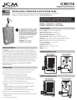
ELECTRICAL SHOCK HAZARD
– Before
installing this unit, turn off power at
the main service panel by removing
the fuse or switching the appropriate
circuit breaker to the OFF position.
WARNING — SHOCK HAZARD — DO NOT OPEN;
ATTENTION – RISQUE DE CHOC – NE PAS OUVRIR
Device is intended to be connected only to panel connection. All
wiring must conform to national, state and local electrical codes.
14AWG wire or larger required. Product contains no serviceable parts.
1. Turn off the main breaker and/or main power to the service disconnect.
2. Remove the cover on service disconnect or the electrical panel.
3. Mount through conduit connection of electrical panel:
3.1 Remove one lock nut and sealing ring on the unit.
3.2 Feed the wires into the electrical panel service disconnect.
3.3 Re-secure the lock nut and sealing ring (see mounting instructions).
4. Route the green wire to the grounding lug and secure.
5. Connect the two black wires and one white wire (see wiring for 120 &
240VAC).
–
For electrical panel:
Connect to closest two-pole breaker (240VAC).
Connect to the closest single-pole breaker (120VAC).
–
For A/C disconnect:
Connect to the disconnect load side terminals.
6. Reinstall cover on service disconnect or the electrical panel.
7. Restore power; LED should be on with 120 VAC present from black to green
and black to white.
8. Close electrical panel or cover.
Service Voltage: 120/240 volt, single phase
Maximum Surge Current: 100,000 amps
Maximum Energy Dissipation: 1,020 joules
Installation Point: Electrical panel, electrical disconnect
Diagnostics: Green light indicates surge suppression present
Enclosure: NEMA Type 4X waterproof metal enclosure
AC Protection Modes: L-L, L-N, L-G, N-G
Conduit Connection: 3/4”
Dimensions: 5.0” L x 3.06” W x 1.75” D
Weight: 0.55 lbs.
The ICM517A is UL Rated as a Type 2 device and must be installed
before the equipment it is intended to protect. It can be installed at the
A/C disconnect or an indoor/outdoor electrical panel. Suitable for use
on a circuit capable of delivering not more than 10,000 rms symmetrical
amperes, 240V max, when protected by a circuit breaker rated 15-60A
maximum and 120V minimum. Device wires should be kept at a minimal
length to increase response time and effectiveness of the control.
Contains no serviceable parts. LED indicates when protect is present.
Limited lifetime product, up to a 3-year $10,000 connected
equipment warranty
MODE OF OPERATION
WIRING DIAGRAM (240 VAC)
WIRING DIAGRAM (120 VAC)
INSTRUCTIONS
SPECIFICATIONS
Indoor Installation
(120 VAC Shown)
Wire Nut
BLK
BLK
Neutral Bus
Field
Ins
tal
led
BLK
Gro
un
d Bus
GRN
ICM 517A
WHT
Outdoor Installation
(120 VAC Shown)
F
U
S
E
F
U
S
E
B
B
R
B
G
Ground
ICM 517A
B
B
Field
Ins
tal
led
BLK
Wire Nut
Indoor Installation
(240 VAC Shown)
BLK
Neutral Bus
Gro
un
d Bus
WHT
Outdoor Installation
(240 VAC Shown)
Ground
F
U
S
E
F
U
S
E
B
B
R
B
G
ICM 517A
ICM 517A
GRN
BLK
ATTENTION:
No replaceable or
repairable parts;
ATTENTION:
Aucune pièce
remplaçable ou reparable
INSTALLATION, OPERATION & APPLICATION GUIDE
For more information on our complete range of American-made products – plus wiring
diagrams, troubleshooting tips and more, visit us at www.icmcontrols.com
ICM517A
Surge Protective Device


