Chore-Time Hyflo Скачать руководство пользователя страница 7

48" and 52" HyfloTM Fans Installation and Operators Instruction Manual

Maintenance

MV1747D

7

IMPORTANT!

 Disconnect Power Prior To Maintaining Or Cleaning The Fan. The fan may start 

automatically causing serious injury or death.

• Service and repair of fans should be done only by a qualified technician.
• Keep the fan clean for maximum life and best performance. 

Do Not spray water on Fan Shaft Bearings 

or Motor.

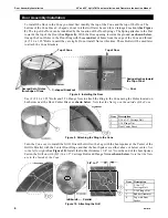
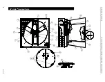
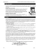
• Periodically check the V-Belt and replace if necessary. A worn Belt will cause a substantial drop in Fan 

performance or it can break and cause Fan failure.


If a Belt rides below the Sheave edge, replace the belt.


(See Figure 15 below)

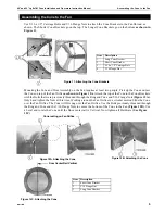
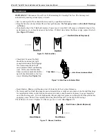
• Check Belt Tension.The Belt 

should be tensioned just tight 
enough to minimize Belt slippage. 
Over tensioning the belt will 
cause premature Belt and Bearing 
wear. With a new Belt the Idler 
Sheave indicator mark should line 
up with the third notch in the Ten-
sioner Housing 

(See Figure 16)

.

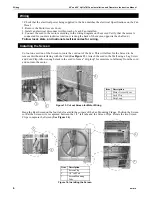
• Keep Shutters, Blades, and Housing clear of obstacles for best air performance.
• The motor and Fan Shaft Bearings are pre-lubricated. Grease zerks are provided on the fan shaft bearings 

for installations where re-lubrication is needed. Add only a small amount of grease to purge impurities 
out of the bearing seals. Use only high quality lithium soap base grease and clean all dirt from zerk before 
applying grease. Chore-Time recommends using Shell Alvania # 2 in the fan shaft bearings.

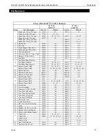
Check Sheaves for wear. Replace if a Sheave groove is worn. 

(See Figure 17)


Maintenance

Bad Belt

Good Belt

1747-054 04/03

Bad Belt (Needs Replaced)

Figure 15. Belt Condition

Third Notch

Idler Sheave Indicator Mark

Figure 16. Idler Sheave Indicator Mark

Bad Sheave

1747-053 04/03

Bad Sheave (Needs Replaced)

Good Sheave

Figure 17. Sheave Condition

Содержание Hyflo

Страница 1: ...16 04 03 Item 48 Hyflo 52 Hyflo 1 41 7 8 106 36 cm 44 111 76 cm 2 59 149 9 cm 64 162 56 cm 3 5 1 8 13 02 cm 5 1 8 13 02 cm 4 12 35 31 37 cm 12 35 31 37 cm 5 2 5 16 5 87 cm 4 1 8 10 48 cm 3 2 Figure 1 Fan Dimensions 4 1 5 MV1747 017 04 03 3 2 3 2 Planning the layout of the spacing between Fans is very important Spacing too close together will cause interference between the discharge Cones The Rough...

Страница 2: ...Note that the Nuts go outside the Posts Remove the Motor from the Crate and attach it to the Motor Support Bracket with 4 5 16 Carriage Bolts and 4 5 16 Flange Nuts as shown Belt Installation Guide the Belt through the Opening in the Motor Support Bracket and loop it over the Motor Sheave Guide the Belt around the Tensioner Sheave and push on it to get enough slack to put the Belt on the Driven Sh...

Страница 3: ...e panels up on edge and curl the Cone around with the smaller diameter of the Cone up as shown below Assemble the final Panels together and allow the Cone to take its shape If the Cone is assembled correctly the Tabs should all be on the Inside of the finished Cone Fasten the Cone Panels together with 4 5 16 x 1 2 Hex Bolts Threaded in from the inside of the finished Cone as shown in Figure 7 Cone...

Страница 4: ... Holes located on both sides near the Door Center Brace as shown below Note that the Nuts go on the outside of the Cone Turn the Cone over to install the Grill Orient the Grill so the Leg with the bent spokes at the Center of the Grill is Parallel with the Center Door Hinge and that the bent Spokes are either above or below center Not to the left or right See Figure 10 Install the Rubber Grommet 3...

Страница 5: ...nd tighten the Nuts at this time Working around the Fan Orifice in a circular motion Slide the Cone over the Fan Orifice The Cone will Fit snug over the Fan Orifice Use the Bolts previously threaded through the Ring and Cone and the 5 16 Flange Nuts to secure the bottom of the Cone to the Fan Figure 12B Use a Level and rotate the Cone until the Door center rail is Vertical Now tighten all Hardware...

Страница 6: ...e cord out of the Fan This will allow for the Screen to be removed without interfering with the Cord See Figure 13 Attach the cord to the Wall using a Lag Screw and Cord Clip Allow enough slack in the cord to form a drip loop for moisture to fall away from the cord and not into the motor Hang the Rear Screen on the four tabs located in the corners of the Fan Mounting Flange Position the Screen so ...

Страница 7: ...mature Belt and Bearing wear With a new Belt the Idler Sheave indicator mark should line up with the third notch in the Ten sioner Housing See Figure 16 Keep Shutters Blades and Housing clear of obstacles for best air performance The motor and Fan Shaft Bearings are pre lubricated Grease zerks are provided on the fan shaft bearings for installations where re lubrication is needed Add only a small ...

Страница 8: ...M Fans Installation and O perators Instruction Manual 8 MV1747D 48 HyfloTM Itemized Parts 3 10 3 4 3 30 3 9 3 16 3 18 3 12 3 15 3 14 3 7 3 6 3 19 3 3 3 5 3 8 3 11 3 13 3 25 3 22 3 23 3 21 3 20 3 26 3 27 3 33 3 29 3 2 3 17 3 32 3 31 3 24 3 1 3 28 ...

Страница 9: ... 51 52 Sheave Driven AK94 40274 21 22 41 42 40274 21 22 41 42 12 Hyflo Top Panel 48671 All 48685 All 13 Hyflo R H Side Panel 48672 2 All 48684 2 All 14 Hyflo L H Side Panel 48672 1 All 48684 1 All 15 Hyflo Bottom Panel 48673 All 48686 All 16 Sheave Driver AK27 1381 23 Sheave Driver AK30 8773 21 22 41 42 8773 21 22 41 42 Sheave Driver AK32 48504 51 52 48504 51 52 17 Screen Clip 36729 All 36729 All ...

Страница 10: ... ifall components of the system are not original equipment supplied by the Manufacturer 3 This product must be purchased from and installed by an authorized distributor or certified representative thereof or the Warranty will be void 4 Malfunctions or failure resulting from misuse abuse negligence alteration accident or lack of proper maintenance shall not be considered defects under the Warranty ...

Отзывы: