


5
Operation
When the switch senses feed, the internal relay is activated immediately, stopping the
system. When feed is removed, the delay is activated and prevents the system from
starting until it has timed out.
Setting the Delay
The Proximity Switch includes an adjustable delay. The delay may be set from 1 sec-
ond to 10 minutes.
A. Use a small screw driver provided to turn the Delay Adjustment Screw (see
Figure 4). Turn the screw counter clockwise until the light stays on. Turn the
screw clockwise one complete revolution. This sets the delay to 1 second.
B. To increase the delay, turn the Delay Adjustment Screw clockwise.
Watch the indicator light; quick flashes = shorter time delay, slow flashes =
longer time delay.
Adjusting the Sensitivity
The Proximity Switch is shipped with the sensitivity preset at the factory. This setting
is adequate for most feed types and conditions. However if the sensitivity does need
to be adjusted, carefully follow these instructions:
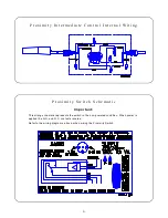
A. Allow power to be supplied to the switch for at least 15 minutes to properly
warm the sensor. See the wiring diagrams in this manual.
B. Set the Proximity Switch time delay to 1 second as specified above.
C. Use a small screw driver to remove the caulk concealing the Sensitivity
Adjustment Screw.
D. Greater switch sensitivity is achieved by turning the Sensitivity Adjustment
Screw clockwise.
Less switch sensitivity is achieved by turning the Sensitivity Adjustment
Screw counterclockwise.
Note the screw orientation before beginning adjustment. Adjust the Sensitiv-
ity Adjustment Screw 1/4 turn, test switch, continue adjusting as required.
F i g u r e 4 . P r o x i m i t y S w i t c h A d j u s t m e n t s ( e n d v i e w o f P r o x i m i t y S w i t c h ) .
Содержание 36880
Страница 7: ...7 This page intentionally left blank...