Chore-Time 36880 Скачать руководство пользователя страница 2

2

F i g u r e   1 .   E n l a r g i n g   t h e   O u t l e t   H o l e s   ( f r o n t   v i e w ) .
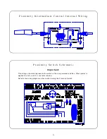
Installation

The Auger Tube with the Intermediate Control must have each hole enlarged, as
shown in Figure 1. This will ensure total feed dropout before the Intermediate Control.
Use a hacksaw and tin snips to enlarge hole size. Be sure there are no burrs inside
the tube to catch the auger.

Install the Proximity Intermediate Control:

Remove the (2) Hex Head Screws securing the Tube Retainer on the Inter-
mediate Control. See Figure 2.

Lift off the Tube Retainer.

Cradle the Feeder Tube in the Control Housing. The Feeder Tube may have
to be turned to allow the pan to hang straight.

Clamp the Control in place by inserting tabs on the Tube Retainer into the
slots on the Control Body. Install and tighten the two hex head screws, re-
moved above.

Figure 3 shows an Intermediate Control installed in the appropriate location.

Key

Description

1

(2) Hex Head Screws

2

Tube Retainer

Key

Description

1

Auger Tube

2

Tube Seam

3

Cut here to enlarge outlet holes.

F i g u r e   2 .   I n t e r m e d i a t e   C o n t r o l   I n s t a l l a t i o n   ( s i d e   v i e w ) .

Содержание 36880

Страница 1: ...Control w On Delay was designed for brood applications The Proximity Intermediate Control uses a Proximity Switch to sense feed and cause the system to start and stop The Proximity Switch has sensitiv...

Страница 2: ...Tube Retainer on the Inter mediate Control See Figure 2 Lift off the Tube Retainer Cradle the Feeder Tube in the Control Housing The Feeder Tube may have to be turned to allow the pan to hang straigh...

Страница 3: ...ion Hopper at the end of the Feeder Line 2 3 Intermediate Control Unit Partition or Curtain Wire the Control the circuit breakers before performing any service work Important constant the black and th...

Страница 4: ...g schematic represents the switch in the non powered condition When power is applied the N O and N C contacts reverse Refer to the wiring diagrams above when wiring the Proximity Switch P r o x i m i...

Страница 5: ...ity The Proximity Switch is shipped with the sensitivity preset at the factory This setting is adequate for most feed types and conditions However if the sensitivity does need to be adjusted carefully...

Страница 6: ...tch Box Cover 27047 10 Gasket 6777 11 Switch Box Cover 6776 12 Danger Decal 2529 480 13 Switch Box 36334 1 14 Proximity Switch Ass y 36881 1 Proximity Switch 34255 Safety Cap 36467 Liquid Tight Conn 2...

Страница 7: ...7 This page intentionally left blank...

Страница 8: ...Time distributor or representative for additional parts and information Chore Time Equipment A Division of CTB Inc P O Box 2000 Milford Indiana 46542 2000 U S A Phone 219 658 4101 Printed in the U S A...

Отзывы: