Содержание HS500

Страница 1: ...ully understand it otherwise any improper repairing and amounting would bring you problems and accident may occur in your use Proper use and maintenance can guarantee ATV being driven safely reduce it...

Страница 2: ...S 6 FASTENERS 6 Torque specifications 6 Self locking fasteners 6 Washers 6 Cotter pins 7 Snap rings and E clips 7 SHOP SUPPLIES 8 Lubricants and Fluids 8 Engine oils 8 Greases 8 Brake fluid 9 Coolant...

Страница 3: ...ent 19 Care 20 Metric micrometer 20 Standard inch micrometer 21 Telescoping and small bore gauges 22 Dial Indicator 22 Compression gauge 23 Multimeter 23 ELECTRICAL SYSTEM FUNDAMENTALS 23 Voltage 24 R...

Страница 4: ...with air temperature below 10 C 50 F 35 Engine is hot 36 Starting the engine after a fall or after the engine stalls 36 Flooded engine 36 ENGINE WILL NOT START 37 Identifying the problem 37 Spark tes...

Страница 5: ...ENGLNE LUBRICATION HIGH OIL CONSUMPTION OR EXCESSIVE 47 Exhaust smoke 47 Low oil pressure 47 High oil pressure 48 No oil pressure 48 Oil level too low 48 Oil contamination 48 CYLINDER LEAK DOWN TEST 4...

Страница 6: ...rake caliper 60 Leaking master cylinder 60 CHAPTER 2 SPECIFICATIONS HOW TO USE CONVERSION TABLE OF UNIT 61 How to use conversion table 61 Definition of unit 61 GEBERAR SPECIFICATIONS 62 ENGINE SPECIFI...

Страница 7: ...1 Changing the coolant 102 Checking the coolant temperature warning light 105 Checking the v belt 106 Cleaning the spark arrester 107 Adjusting the brake pedal 108 Checking the brake fluid level 109 C...

Страница 8: ...Changing the headlight bulb 129 Changing the tail brake light bulb 130 CHAPTER 4 ENGINE ENGINE NOTE 132 ENGINE REMOVAL 133 CYLINDER HEAD AND CYLINDER HEAD COVER 135 ROCKER ARMS AND CAMSHAFT 140 VALVE...

Страница 9: ...of steering bar 209 Diassembling the parts of steering column 209 Checking and the steering operation system 211 Installing the steering operation system 212 Installing the steering handle 215 BRAKE S...

Страница 10: ...d rear wheel rim 246 Checking the wheel tyre 247 Checking the wheel hub 247 Installing the wheel hub 248 Installing the wheel tyre 248 Specification of wheel and tyre 249 TRANSMISSION SYSTEM 250 Front...

Страница 11: ...arms 280 Checking the rear shock absorber 280 Installing the rear arms and rear shock absorber 281 COOLING SYSTEM 282 Radiator 282 Checking the radiator 284 Installing the radiator 285 Water pump 286...

Страница 12: ...LIGHTING SYSTEM 320 If the headlights fail to come on 320 If the taillights fail to come on 321 SIGNALING SYSTEM 322 CIRCUIT DIAGRAM 322 TROUBLESHOOTING 323 CHECKING THE SIGNAL SYSTEM 324 If the brake...

Страница 13: ...rs 346 Throttle body assembly with stepper motor 350 Engine coolant temperature sensor 352 Intake air pressure and temperature sensor 353 Oxygen sensor 353 Ignition coil 353 Fuel pump module 357 EMS F...

Страница 14: ...LE HANDLING 369 Unstable handling 369 LIGHTING SYSTEM 370 Head light is out of work 370 Bulb burnt out 370 CHAPTER 9 HS600ATV SERVICE MANUAL HS600ATV SUPPLEMENTARY 371 SPECIFICATIONS 372 Geberar speci...

Страница 15: ...terms WARNING CAUTION and NOTE have specific meaning in this manual emphasizes areas where injury or even death could result from negligence Mechanical damage may also occur WARNINGS are to be taken...

Страница 16: ...Fuel cock 15 Battery 16 Fuses 17 Engine oil dipstick 18 Tail brake lights 19 Recoil starter 20 Coolant reservoir 21 Drive select lever box check hose 22 V belt cooling duct check hose 23 Rear brake le...

Страница 17: ...CODE 3 Frame No Frame No is carved in the lower right side of Figure Engine No Engine NO Is carved on the right side of the engine Figure PDF compression OCR web optimization using a watermarked evalu...

Страница 18: ...hammering compressed air and chemicals 11 Wear the correct clothing for the job Tie up or cover long hair so it does not get caught in moving equipment 12 Do not carry sharp tools in clothing pockets...

Страница 19: ...ormed in the home garage Many types of chemical cleaners and solvents are available for shop use Most are poisonous and extremely flammable To prevent chemical exposure vapor buildup fire and serious...

Страница 20: ...lure and or damage Torque Specifications The material used in the manufacturing of the ATV may be subjected to uneven stresses if the fasteners of the various subassemblies are not installed and tight...

Страница 21: ...nt Cotter pins are available in various diameters and lengths Measure the length from the bottom of the head to the tip of the shortest pin Snap Rings and E clips Snap rings Figure 1 are circular shap...

Страница 22: ...lassification The API and SAE information is on all oil container labels Two letters indicate the API service classification The number or sequence of numbers and letter 10W 405G for example is the oi...

Страница 23: ...one based DOT 5 is not compatible with other brake fluids may cause brake system failure When adding brake fluid only use the fluid recommended by the manufacturer Brake fluid will damage any plastic...

Страница 24: ...speed up the removal process and prevent damage to the mating surface that may be caused by using a scraping tool Most of these types of products are very caustic Follow the gasket remover manufactur...

Страница 25: ...o basic types are the slotted tip flat blade and the Phillips tip These are available in sets that often include an assortment of tip size and shaft lengths As with all tools use a screwdriver designe...

Страница 26: ...s and is subject to slipping if under heavy force or if the tool or fastener is worn A box end wrench is preferred in most instances especially when braking loose and applying the final tightness to a...

Страница 27: ...r air tools Use hand sockets with hand driven attachments of the square hole that accepts Do not use hand sockets with air or impact tools because they may shatter and cause injury Always wear eye pro...

Страница 28: ...xtension to tighten a fastener to a measured torque Torque wrenches come in several drive sizes 1 4 3 8 1 2 and 3 4 and have various methods of reading the torque value The drive size indicates the si...

Страница 29: ...he adapter increases or in some cases reduces the effective lever length as measured along the centerline of the torque wrench L is the lever length of the wrench as measured from the center of the dr...

Страница 30: ...cialized pliers with tips that fit into the ends of snap rings to remove and install them Snap ring pliers Figure 17 are available with a fixed action either internal or external or convertible one to...

Страница 31: ...ice Each type of measuring instrument is designed to measure a dimension with a certain degree of accuracy and within a certain range When selecting the measuring tool make sure it is applicable to th...

Страница 32: ...so it can be removed with a slight drag Some calipers require calibration Always refer to the manufacturer s instructions when using a new or unfamiliar caliper To read a vernire Calipers refer to Fi...

Страница 33: ...st savings but its overall size may make it less convenient When reading a micrometer numbers are taken from different scales and added together The following sections describe for and read the measur...

Страница 34: ...orrosion Metric micrometer The standard metric micrometer Figure 24 is accurate to one one hundredth of a millimeter 0 01 mm The sleeve line is graduated in millimeter and half millimeter increments T...

Страница 35: ...it Each mark equals 0 001 in One complete turn of the thimble will align its zero mark with the first mark on the sleeve or 0 025 in To read a standard inch micrometer perform the following steps and...

Страница 36: ...cause there is no built in release Excessive tightening can damage the bore surface and damage the tool Remove the gauge and measure the outside dimension Figure 30 Small bore gauges are typically use...

Страница 37: ...ific test meter Results may vary if using a meter not recommended by the manufacturer Such requirements are noted when applicable Ohmmeter analog calibration Each time an analog ohmmeter is used or if...

Страница 38: ...e can cause the coil to malfunction even though it tests acceptable during a resistance test Resistance generally Increases with temperature Perform all testing with the component or circuit at room t...

Страница 39: ...ing a hydraulic press If a press is not available have these operations performed by a shop equipped with the necessary equipment Do not use makeshift equipment that may damage the motorcycle 13 Repai...

Страница 40: ...e for removing the remaining portion If a large portion of the remainder projects out try gripping it with locking pliers If the projecting portion is too small file it to fit a wrench of cut a slot i...

Страница 41: ...nstall the stud to the height noted in Step 1 or its torque specification 9 Remove the stud removal tool or the two nuts cD PI Removing Hoses When removing stubborn hoses do not exert excessive force...

Страница 42: ...s next to the inner bearing race See Figure 40 2 When using a hammer to remove a bearing from a shaft do not strike the hammer directly against the shaft Instead use a brass or aluminum rod between th...

Страница 43: ...th outer and inner bearing races In this situation install a spacer underneath the driver tool so that pressure is applied evenly across both races See Figure 46 If the outer race is not supported as...

Страница 44: ...ases as required to remove all traces of oil and other chemical deposits a Heat the housing to approximately 100 C 212 F in an oven or on a hot plate An easy way to check that it is the proper tempera...

Страница 45: ...l it is to the correct depth or flush as noted during removal Never install a seal by hitting against the top of it with a hammer prevent damage to the STORAGE Several months of non use can cause a ge...

Страница 46: ...n a work stand with both wheels off the ground 10 Cover the ATV with old bed sheets or something similar Do not cover it with any plastic material that will trap moisture Returning the ATV to Service...

Страница 47: ...le may develop problems that require trouble shooting If the problem cannot be solved Stop and evaluate all conditions prior to the problem If the motorcycle must be taken to a repair facility the mec...

Страница 48: ...ch would cause the engine to stall Engine is warm 1 Shift the transmission into neutral 2 Confirm if the fuel is in upper or below retied in the tank 3 Release the hot start lever as soon as the engin...

Страница 49: ...accelerator pump can overly richen the air fuel mixture which may cause the engine to stall Engine cold with air temperature above 35 C 95 F 1 Shift the transmission into neutral 2 Turn the fuel valv...

Страница 50: ...e engine fails to start after several attempts it is probably flooded This situation occurs when too much fuel is drawn into the engine and the spark plug fails to ignite it The smell of gasoline is o...

Страница 51: ...ing the engine If the plug tip is dry fuel is not reaching the engine Refer to Fuel System in this chapter If there is fuel on the spark plug and the engine will not start the engine may not have adeq...

Страница 52: ...t the ignition system is working correctly CAUTION After removing the direct ignition coil or spark plug cap and before removing the spark plug in Step 1 clean the area around the spark plug with comp...

Страница 53: ...is can be due to improper use or a stuck choke valve in the carburetor 2 Incorrect hot start valve operation This situation can be due to improper use or incorrect hot start valve adjustment 3 Plugged...

Страница 54: ...wing engine components a Broken valve springs b Stuck or leaking valves c Worn or damaged camshaft lobes d Incorrect valve timing due to incorrect camshaft installation or a mechanical failure Engine...

Страница 55: ...f the engine speed in creased according to throttle position Perform Step 3 If the engine speed did not increase Check CVT a Warped clutch plates discs b CVT spring 3 Test rides the ATV and accelerate...

Страница 56: ...ese conditions will cause an air leak 3 Perform the spark test in this chapter Note the following a If the spark is good Go to Step 4 b If the spark is weak Perform the Peak Voltage Testing 4 Check th...

Страница 57: ...e b If there is fuel present on the plug tip And the engine has spark Check for an excessive intake air leak or the possibility of contaminated or stale fuel NOTE If the ATV was not used for some time...

Страница 58: ...the engine heats up to normal operating temperature the water evaporates and exits the engine through the crankcase vent system However if the ATV is ridden for short trips or repeatedly started and s...

Страница 59: ...tor cap coolant drain plug or disconnect any coolant hose immediately after or during engine operation Scalding fluid and steam may be blown out under pressure and cause serious injury When the engine...

Страница 60: ...n engine damage Power Loss Refer to Poor Engine Performance in this chapter Engine Noises Unusual noises are often the first indication of a developing problem Investigate any new noises as soon as po...

Страница 61: ...lve train noise Check for the following a Excessive valve clearance b Worn or damaged camshaft c Damaged camshaft d Worn or damaged valve train components e Damaged valve lifter bore s f Valve stickin...

Страница 62: ...ls 6 Piston rings incorrectly installed during engine overhaul 7 External oil leakage 8 Oil leaking into the cooling system Oil Contamination 1 Blown head gasket allowing coolant to leak into the engi...

Страница 63: ...4 Install the threaded hose adapter from the leak down kit Then install the leak down gauge onto the hose 5 Remove the ignition timing hole cap from the left crankcase cover 6 Remove the crankshaft h...

Страница 64: ...ot turn the crankshaft as required then relock the holding tool in position 9 Remove the radiator cap and the oil filler cap 10 Perform a cylinder leak down test by applying air pressure to the combus...

Страница 65: ...ed circuits are faulty at the same time the probable cause is a poor ground connection or a blown fuse if used As with all troubleshooting procedures analyze typical symptoms in a systematic manner Ne...

Страница 66: ...heat related problem occur when a component creates its own heat as it starts to fail or go bad a Troubleshoot the problem to help isolate the problem or area b To check a connector Perform a continu...

Страница 67: ...if battery voltage is present in any given circuit The voltmeter unlike the test light also indicates how much voltage is present at each test point When using a voltmeter attach the positive lead to...

Страница 68: ...tiply the meter reading by the ohmmeter scale For example a meter reading of 5 multiplied by the Rx100 scale is 5000 ohms of resistance CAUTION Never connect an ohmmeter to a circuit which has power a...

Страница 69: ...tor This type of test can be performed with a test or a voltmeter A voltmeter gives the best results NOTE If using a test light It does not make any difference which test lead is attached to ground 1...

Страница 70: ...drop are loose or contaminated connectors and poor ground connections Peak voltage test Peak voltage tests check the voltage output of the ignition coil and ignition pulse generator at normal cranking...

Страница 71: ...oltmeter attached to the fuse terminals wiggle the wiring harness relating to the suspect circuit at various intervals Start next to the fuse terminal a work systematically away from the fuse terminal...

Страница 72: ...ake pads for wear If it does not appear that there is an increase in pad wear check the brake hoses lines and banjo bolts for leaks 3 Leak in the brake system 4 Contaminated brake fluid 5 Plugged brak...

Страница 73: ...rd Brake Lever or Pedal Operation When applying the brakes and there is sufficient brake performance but the operation of brake lever feels excessively hard check for the following possible causes 1 C...

Страница 74: ...eals 2 Damaged cylinder bore 3 Loose caliper body bolts 4 Loose banjo bolt 5 Damaged banjo bolt washers 6 Damaged banjo bolt threads in caliper body Leaking Master Cylinder 1 Damaged piston secondary...

Страница 75: ...c cm3 0 03527 oz IMP liq Volume capacity cc cm3 0 06102 cu in lit liter 0 8799 qt IMP liq lit liter 0 2199 gal IMP liq kg mm 55 997 lb in Others kg cm2 14 2234 psi Ib in2 Centigrade 9 5 CC 32 Fahrenhe...

Страница 76: ...d recoil starter Wet sump Oil type or grade Engine oil 4 14 32 50 68 11111186 104 122 F Le I API service SE SF SG type or higher SAE80 API GL 4 Hypoid gear oil SAE80 API GL 5 Hypoid gear oil SAE 20W40...

Страница 77: ...and operation 0 75 2 45 5 3595 30 17x41 21x24 18 3 2230 26 21x41 21x24 18 3 8282 25 17x41 21x24 18 Chassis Frame type Camber angle Trail Toe in Steel tube frame 5 26 0mm 1 02 in 0 10 mm 0 00 0 39 in T...

Страница 78: ...m 7 3 in 185 mm 7 3 in Electrical Ignition system Generator system Battery type Battery capacity C D I A C magneto MS12 19CL BS 12 V 21Ah Headlight type Bulb wattage X quantity Headlight Tail brake li...

Страница 79: ...ft Drive method Cam dimensions Chain drive Left 0 A Intake Exhaust 30 06 30 16 mm 1 1835 1 1874 in 35 69 35 79 mm 1 4051 1 4091 in 30 11 30 21 mm 1 1854 1 1894 in 36 50 36 60 mm 1 4370 1 4409 in 1 179...

Страница 80: ...ead diameter IN 29 9 30 1 mm 1 1772 1 1850 in EX 31 9 32 1 mm 1 2559 1 2638 in B face width IN 2 25 mm 0 0900 in 2 26 mm EX 0 0890 in 0 9 1 1 mm 1 6 mm C seat width IN 0 0354 0 0433 in 0 0630 in 0 9 1...

Страница 81: ...Free length IN 32 63 mm 1 28 in 31 0 mm EX 36 46 mm 1 44 in 1 22 in Set length valve closed IN 27 5 mm 1 08 in 34 6 mm EX 31 0 mm 1 22 in 1 36 in Compressed pressure installed IN 100 0 115 7 N 10 20 1...

Страница 82: ...side diameter 21 991 22 000 mm 0 8650 in 0 8658 0 8661 in Piston rings Top ring T B Type Barrel ____ Dimensions BxT 1 2 x3 8 mm ____ 0 0472 x0 1496 in End gap installed 0 30 0 45 mm 0 70 mm 0 0118 0 0...

Страница 83: ...n 0 010 0 025 mm 0 0004 0 0010 in 0 03 mm 0 0012 in 0 03 mm 0 0012 in 1 0 mm 0 0394 in T F Crank width A Runout limit C1 C2 Big end side clearance Big end radial D E clearance Balancer Balancer drive...

Страница 84: ...g cm2 62 7 90 6 psi 65 Kpa 0 65 kg cm2 9 2 psi at 1 500 r min Cylinder head 0 23 mm 0 0091 in 0 17 mm 0 0067 in 0 24 mm 0 0094 in Water pump Type Reduction ratio Single suction centrifugal pump 32 31...

Страница 85: ...10 76 in 44 1 N mm 4 41 kg mm 246 95 lb in 117 7N mm 11 77kg mm 659 08 lb in 0 60 mm 0 2 36 in 60 81 mm 2 36 3 15 in Front wheel Type Rim size Rim material Rim runout limit radial lateral Panel wheel...

Страница 86: ...ylinder inside diameter 27 0 mm 1 06 in Brake fluid type DOT 4 Rear disc brake Type Single or Dual Disc outside diameter x thickness 165 0 x 5 0 mm 6 50 x 0 20 in Pad thickness inner 5 6 mm Pad thickn...

Страница 87: ...plug cap Resistance 10 kO Charging system Nominal output Charging coil resistance color 14 V 23 A at 5 000 r min 0 32 0 430at 20 V 68 F White White Rectifier regulator Regulator type No load regulate...

Страница 88: ...Brush overall length 12 5 mm 0 49 in 5 mm 0 20 in Spring force 7 65 10 01 N 780 1 021 g 27 5 36 0 oz Commutator diameter 28 mm 1 10 in Mica undercut 0 7 mm 0 03 in 27 mm 1 06 in Starter relay Amperage...

Страница 89: ...0 14 Rocker arm shaft stopper Bolt M6 2 10 1 0 7 2 Valve adjusting locknut M6 5 14 1 4 10 Engine oil drain bolt M14 1 30 3 0 22 Oil filter cartridge union bolt M20 1 63 6 3 4 6 Oil filter cartridge M2...

Страница 90: ...r Bolt M6 2 10 1 0 7 2 A C magneto cover Bolt M6 12 10 1 0 7 2 Starter clutch Bolt M8 3 30 3 0 22 Clutch carrier assembly Nut M22 1 160 16 0 115 Stake Clutch housing assembly Bolt M6 9 10 1 0 7 2 Bear...

Страница 91: ...Radiator bracket and frame Bolt M6 4 7 0 7 5 1 Fuel pump Bolt M6 2 7 0 7 5 1 Fuel tank Bolt M8 2 30 3 0 22 Muffler stay Bolt M6 2 11 1 1 8 0 Muffler and exhaust pipe Bolt M8 1 20 2 0 14 Muffler brack...

Страница 92: ...tial gear case M8 25 2 5 18 Rear driving axle gear case and frame M10 70 7 0 51 Rear driving axle gear case filler plug M20 23 2 3 17 Rear driving axle gear case drain plug M10 20 2 0 14 Ring gear bea...

Страница 93: ...r M10 19 1 9 13 Pedal holder assembly and frame M8 16 1 6 11 Brake master cylinder and pedal holder assembly M8 16 1 6 11 Secondary brake master cylinder kit stopper bolt M6 9 0 9 6 5 Brake rod locknu...

Страница 94: ...frame M10 64 6 4 46 Support frame enclosure and side frame enclosure M10 64 6 4 46 Top frame enclosure and side frame enclosure M10 64 6 4 46 Seat support and frame M8 16 1 6 11 Footrest plate and fra...

Страница 95: ...rn and progressive stages until the specified tightening torque is reached Unless otherwise specified tightening torque specifications require clean dry threads Components should be at room temperatur...

Страница 96: ...r idle gear shaft Apply molybdenum disulfide grease Starter wheel gear Apply engine oil Clutch housing assembly shaft end Apply lithium soap based grease Clutch carrier assembly Apply engine oil One w...

Страница 97: ...ase frease Joint of front brake cable Light lithium base frease Front brake lever axle and rear brake lever axle Light lithium base frease Adjusting nut and pin of rear brake cable Light lithium base...

Страница 98: ...HIC CHART Hydrographic chart I Pressure splash Cylinder head Cylinder body Water pump Water tank Inner cycle outside cycle 84 PDF compression OCR web optimization using a watermarked evaluation copy o...

Страница 99: ...Piston pin Automatic centrifugal clutch Spindle Middle gearbox Connecting rod Middle shaft crank i Camshaft Valve Fine filter Atmospheric valve Oil pump Rocker Sprocket chamber Rough filter 85 PDF co...

Страница 100: ...in wet of dusty areas Front brake Check operation fluid leakage See NOTE page 8 Correct if necessary 0 0 0 0 0 Rear brake Check operation Adjust if necessary 0 0 0 0 0 Wheel Check balance damage Repa...

Страница 101: ...cessary 0 0 0 Engine oil Replace Warm engine before draining 0 0 0 0 Engine oil strainer Clean 0 0 0 0 Engine oil filter cartridge Replace 0 0 0 0 Final gear oil Check oil level oil leakage Replace 0...

Страница 102: ...Dead Center TDC on the compression stroke Remove driver seat passenger seat console 1 Remove following parts CD Valve cover exhaust 0 spark plug cap 0 Valve cover intake 0 spark plug 88 2 Remove the...

Страница 103: ...ckness gauge gap Regulation 0 Regulator 0 Adjust tools Loosen the locknut Insert a thickness gauge between the adjuster end and the valve end Turn the adjuster 0 clockwise or counterclockwise with the...

Страница 104: ...rting engines thorough warm machine 2 Remove driver seat console Refer to SEATS in chapter 5 3 Install Engine tachometer 4 Confirm speed Standard Engine Idle speed Engine idle speed 1 400 100 r min Be...

Страница 105: ...er Throttle Valves ED Throttle Cable 1 Remove following parts driver seat console 2 Remove Throttle valve cover 0 3 Check throttle cable Slack 0 Remove the slack 4 Adjust throttle cable a Will loosen...

Страница 106: ...se to fully open position If the distance is out of specification adjust it as described below starter plunger stroke distance 13mm 0 51in A Fully closed position IR Fully open position c Pull back th...

Страница 107: ...ld be adjusted Wear damage Replace insulator 0 Abnormal color Replace Normal color is a medium to light tan color 4 Clean the spark plug with a spark plug cleaner or wire brush 5 Install spark plug 18...

Страница 108: ...1 500 r min b Remove As manhole covers 0 c Visually check the stationary pointer 0 to verify it is within the required firing rangeOindicated on the flywheel Incorrect firing range Check the pulser co...

Страница 109: ...ressure Check the cylinder head valve surfaces and piston crown for carbon deposits Below the minimum pressure Check the accumulation carbon in the firebox of the cylinder head and accumulation carbon...

Страница 110: ...CKING THE ENGINE OIL LEVEL 1 Place the vehicle on a level surface 2 Remove driver seat console Refer to SEATS in chapter 5 3 Check engine oil level Oil level should be between the maximum Di and minim...

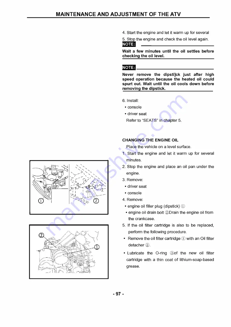
Страница 111: ...NGINE OIL Place the vehicle on a level surface 1 Start the engine and let it warm up for several minutes 2 Stop the engine and place an oil pan under the engine 3 Remove driver seat console 4 Remove e...

Страница 112: ...vel Oil quantity Periodic oil change The oil capacity after the engine is disassembled and reassembled 1 9L The oil should be put into the engine for after all the oil is drawn out 1 8L 8 Install engi...

Страница 113: ...ge Refer to THE ENGINE in chapter 4 d Start the engine after solving the problem s and check the engine oil pressure again e Tighten the oil gallery bolt to specification Oil gallery bolt 17 Nm 1 7 m...

Страница 114: ...ilter element NOTE Never operate the engine with the air filter element removed This will allow unfiltered air to enter causing rapid wear and possible engine damage Additionally operation without the...

Страница 115: ...d be wet but not dripping 4 Install air filter element air filter case cover NOTE To prevent air leaks make sure that the sealing surface of the element matches the sealing surface of the case driver...

Страница 116: ...ter may be used if distilled water is not available 2 Drain coolant from the coolant reservoir 3 Connect coolant reservoir hose 4 Remove coolant drain bolt water pump Di along with the copper washer 5...

Страница 117: ...er pump T R 10 Nm 1 0 m kg 7 2 ft lb 11 Connect water pump inlet hose coolant outlet hose 12 Remove air bleed bolt 0 13 Fill cooling with the specified amount of the recommended coolant Recommended an...

Страница 118: ...f coolant comes into contact with painted surfaces immediately wash them with water Do not mix different types of antifreeze NOTE Adding water instead of coolant lowers the antifreeze content of the c...

Страница 119: ...in chapter 4 NOTE Before checking the coolant level wait a few minutes until the coolant has settled Close the hood Install driver seat Refer to SEATS in chapter 5 CHECKING THE COOLANT TEMPERATURE WAR...

Страница 120: ...warning light comes on momentarily Coolant temperature and electrical circuit are OK Go ahead with riding Coolant temperature warning light does not come on Check the electrical circuit CHECKING THE V...

Страница 121: ...nd secondary sheave Install the V belt NOTE Install the V belt so that its arrow faces the direction shown in the illustration Remove the bolts 2 Install drive belt cover driver seat CLEANING THE SPAR...

Страница 122: ...the bolt 1 and tighten it Start the engine and rev it up approximately twenty times while momentarily creating exhaust system back pressure by blocking the end of the muffler with a shop towel Stop th...

Страница 123: ...p of the brake fluid reservoir top is horizontal 2 Lift the hood up 3 Check brake fluid level Fluid level is under MIN CD line Fill up NOTE Brake fluid may erode painted surfaces or plastic parts Alwa...

Страница 124: ...ace the brake pads as a set Refer to FRONT AND REAR BRAKES in chapter 5 Brake pad wear limit 1 5 mm 0 06 in 3 Operate the brake pedal 4 Install front wheels CHECKING THE REAR BRAKE PADS 1 Check brake...

Страница 125: ...C BRAKE SYSTEM WARNING Bleed the brake system if The system has been disassembled A brake hose or brake pipe have been loosened or removed The brake fluid has been very low The brake operation has bee...

Страница 126: ...the pedal i Repeat steps e to h until all the air bubbles have disappeared from the fluid j Tighten the bleed screw Front brake caliper bleed screw 6 Nm 0 6 m kg 4 3 ft Ib Rear brake caliper bleed scr...

Страница 127: ...sen both locknuts 0 WARNING The select lever shift rod locknut select lever side has left handed threads To loosen the locknut turn it clockwise c Tighten the locknuts 0 ADJUSTING THE BRAKE LIGHT SWIT...

Страница 128: ...l should be up to the brim of the hole Oil level low Add oil to the proper level Recommended oil SAE 80 API GL 4 Hypoid gear oil WARNING Take care not allow foreign material to enter the final gear ca...

Страница 129: ...rim of hole Oil level low Add oil to proper level WARNING Take care not allow foreign material to enter the differential gear case 4 Install oil filler plug 23 Nm 2 3 m kg 17 ft lb CHANGING THE DIFFER...

Страница 130: ...ay start leaking from the differential gear case breather hose Therefore check the quantity of the oil not its level WARNING Take care not to allow foreign material to enter the differential gear case...

Страница 131: ...steering bar leftward and or rightward Then roate from left to right lightly If the ball pin unit of steering tension rod have any vertical clearance replace it Refer to secrtion Steering ststem of ch...

Страница 132: ...the ATV will still go ATV left and right even though Operate the ATV to go forward straightly with steering bar easily causing to getting out of contor and accident After adjusting the toe in correctl...

Страница 133: ...pring preload Turn the adjuster CD to increase or decrease the spring preload Standard position 2 Minimum Soft position 1 Maximum Hard position 5 ADJUSTING THE REAR SHOCK ABSORBERS WARNING Always adju...

Страница 134: ...g conditions The following are minimums Front 31 5Kpa 48 2Kpa Rear 31 5Kpa 48 2Kpa c Use no more than Front 38Kpa 250Kpa Rear 38Kpa 250Kpa when seating the tire beads Higher pressure may cause the tir...

Страница 135: ...essures must be equal in both front tires and equal in both rear tires 2 Check tire surfaces Wear damage 4 Replace Tire wear limit 0 Front and rear 3 0 mm 0 12 in WARNING It is dangerous to ride with...

Страница 136: ...ay result so replace a damaged cable as soon as possible 1 Check cable sheath Damage Replace cable operation Unsmooth operation Lubricate or replace NOTE Hold the cable end up and apply several drops...

Страница 137: ...es Keep batteries and electrolyte out of reach of children Avoid bodily contact with electrolyte as it can cause severe burns or permanent eye injury First aid in case of bodily contact External Skin...

Страница 138: ...ttery by measuring the specific gravity of the electrolyte Therefore the charge of the battery has to be checked by measuring the voltage at the battery terminals 1 Remove battery case cover disconnec...

Страница 139: ...s e Charge of the battery 20 30 2 Charge battery refer to the appropriate charging method illustration WARNING Do not quick charge a battery NOTE Never remove the MF battery sealing caps Do not use a...

Страница 140: ...open circuit voltage of an MF battery stabilizes about 30 minutes after charging has been completed Therefore wait 30 minutes after charging is completed before measuring the open circuit voltage Cha...

Страница 141: ...utes Is the standard charging amperage exceeded NO If the amperage does not exceed the standard charging amperage after 5 minutes replace the battery If the required charging time exceeds 5 hours it i...

Страница 142: ...amperage written on the battery NO Charge the battery until the charging voltage reaches 15 V NOTE Set the charging time to a maximum of 20 hours Ammeter Voltmeter This type of battery charger cannot...

Страница 143: ...m vertically turn the adjuster CD in or out Turning in Headlight beam raised Turning out Headlight beam lowered CHANGING THE HEADLIGHT BULB Remove Lift the hood up headlight bulb holder cover 0 headli...

Страница 144: ...f the bulb Keep it free from oil otherwise the transparency of the glass life of the bulb and luminous flux will be adversely affected If oil gets on the bulb thoroughly clean it with a cloth moistene...

Страница 145: ...n 2 Install bulb new Secure the new bulb with the tail brake light bulb holder NOTE Avoid touching the glass part of the bulb Keep it free from oil otherwise the transparency of the glass life of the...

Страница 146: ...and nuts 6 Make sure sealing bolt with the sealant must be replaced 7 Make sure to use new bearing when remove assembly set up by pressure 8 Determined axial and radial clearance of inner and outer b...

Страница 147: ...nifold Remove the parts in the order listed 1 Carburetor 1 2 Carburetor joint intake manifold 1 3 Intake manifold 1 4 Drain plug 1 For installation reverse the removal procedure 133 PDF compression OC...

Страница 148: ...il and cotton yarn 2 INSTALL Install intake manifold Install intake manifold bolt Install carburetor joint Install carburetor NOTE When installed don t make an object from the intake fell into the cab...

Страница 149: ...pper washer 7 3 Oil delivery pipe 3 1 4 Oil delivery pipe 2 1 5 Spark plug 1 6 Tappet cover intake 1 7 Tappet cover exhaust 2 8 Timing chain tensioner cap bolt 1 9 Timing chain tensioner gasket 1 1 10...

Страница 150: ...NGINE No Part Name Qty Remarks 13 Thermo switch 1 1 For installation reverse the removal procedure 136 PDF compression OCR web optimization using a watermarked evaluation copy of CVISION PDFCompressor...

Страница 151: ...exhaust CD tappet cover intake 0 Cracks damage Replace 0 rings 0 NOTE When installing new replacement washer and apply wheel bearing grease LS 4 Removing the screwdriver and slowly release the timing...

Страница 152: ...der head Scratches damage Replace the cylinder head cover and cylinder head as a set cylinder head water jacket Mineral deposits rust Eliminate 2 INSTALL 1 Installing the cylinder head cover cylinder...

Страница 153: ...ckwise with a thin screwdriver CD until it stops c With the screwdriver still inserted into the timing chain tensioner install the timing chain tensioner and gasket onto the cylinder block Then tighte...

Страница 154: ...1 Plug O ring 1 1 2 Rocker arm shaft stopper 2 3 Rocker arm shaft 2 1 4 Rocker arm 3 1 5 Rocker arm shaft3 O ring 1 1 6 Rocker arm 4 1 7 Rocker arm shaftl O ring 1 1 8 Rocker arm 1 1 9 Rocker arm 2 1...

Страница 155: ...cam guide plate 4 14 Camshaft sprocket 5 15 Camshaft 5 16 Cylinder head 2 17 Cylinder head gasket 1 For installation reverse the removal procedure 141 PDF compression OCR web optimization using a wate...

Страница 156: ...cation Replace Rocker arm inside diameter repairing limit value 012 038mm d Check the surface of the rocker arm shafts Worn pitting scratches Replace e Measure the external diameter of rocker arm shaf...

Страница 157: ...0 Timing chain 0 Sprocket 4 Checking the decompression system decompression system Check while the camshaft sprocket is installed on the camshaft a Check that the decompressor lever pin 0 projects fro...

Страница 158: ...ft Do not install the bolts Then install the timing chain on the camshaft sprocket NOTE Make sure the small holes on the camshaft face upward d Align the notches 0 on the decompressor cams with the pr...

Страница 159: ...wdriver into the timing chain tensioner hole and push the timing chain guide intake side inward f Remove the retaining wire 145 PDF compression OCR web optimization using a watermarked evaluation copy...

Страница 160: ...nder head cover 1 Valve cotter 10 2 Valve spring retainer 5 3 Intake valve spring 3 4 Exhaust valve spring 2 5 Intake valve 3 6 Exhaust valve 2 7 Valve stem seal 5 8 Valve spring seat 5 For installati...

Страница 161: ...seats Pitting wear Reface the valve seat 2 MEASURE 1 Measure The valves surface width Repairing limit value 2 0mm stem to guide clearance Stem to guide clearance valve guide inside diameter valve ste...

Страница 162: ...seat to make a clear pattern c Measure the valve seat width Where the valve seat and valve face made contact blueing will have been removed Valve spring free length Valve spring squareness Out of spe...

Страница 163: ...alve seat is to wide or narrow or cracked grind it to ensure impermeability 3 Lap valve face valve seat NOTE After reface the valve seat or replacing the valve and valve guide the valve seat and valve...

Страница 164: ...pattern h Measure the valve seat width again If the valve seat width is out of specification reface and relapse the valve seat 3 INSTALL 1 Apply molybdenum disulfide oil onto the valve stem and valve...

Страница 165: ...valve cotters onto the valve stem lightly tap the valve tip with a piece of wood CAUTION Hitting the valve tip with excessive force could damage the valve PDF compression OCR web optimization using a...

Страница 166: ...pump outlet hose Cylinder head 1 Coolant inlet joint 1 2 Cylinder O ring 1 1 3 Cylinder gasket 1 4 Dowel pin 2 5 Piston pin clip 2 6 Piston pin 1 7 Piston 1 8 Piston ring set 1 For installation rever...

Страница 167: ...n piston pin Blue discoloration grooves Replace then check the lubrication system 2 MEASURE At the top the middle and the bottom of the piston stroke NOTE Measure the bore diameter at directions of ri...

Страница 168: ...0 08mm 0 13mm 2nd ring 0 03 0 07mm 0 13mm piston pin to piston clearance a Measure the piston pin outside diameter Repairing limit value 0 02mm b Measure the piston pin bore inside diameter Repairing...

Страница 169: ...arrow mark a on the piston points to the exhaust side of the engine Before installing the piston pin clip cover the crankcase with a clean rag to prevent the piston pin clip from falling into the cran...

Страница 170: ...A C magneto Drive belt cover Engine oil Coolant 1 Hand starter the component 1 2 Bolt 4 3 Washer 4 4 Starter driven gear parts 1 5 A C magneto coupler 2 6 A C magneto cover gasket 1 1 7 Dowel pin 2 8...

Страница 171: ...r 1 12 Wood ruff key 1 13 Starter wheel gear 1 14 Washer 1 15 Starter idle gear shaft 1 16 Bearing 1 17 Starter idle gear 1 For installation reverse the removal procedure 157 PDF compression OCR web o...

Страница 172: ...ter wheel gear onto the starter clutch and hold the starter clutch NOTE Install the starter wheel gear with the groove a facing the A C magneto rotor b Turn the starter wheel gear counterclockwise CD...

Страница 173: ...rotor rotates smoothly If not reinstall the key and rotor dowel pins gasket New replacement A C magneto cover 10Nm NOTE When installing the A C magneto cover use a long rod to hold the A C magneto rot...

Страница 174: ...washer 1 1 2 Balancer driven oil pump drive gear 1 3 Chain 1 4 Straight key 1 5 Oil pump driven gear 1 6 Plate 1 7 Balancer drive gear 1 8 Spring 8 9 Pin 4 10 Timing chain guide intake side 1 11 Timi...

Страница 175: ...Excessive noise during operation Replace the balancer drive gear and balancer driven gear as a set 3 Checking the timing chain and guides timing chain Cracks stiff v Replace the timing chain and cams...

Страница 176: ...lock washer new replacement balancer driven gear nut 0 110Nm NOTE Place an aluminum plate between the teeth of the balancer drive gear and balancer driven gear CI Apply the molybdenum disulfide grease...

Страница 177: ...in the order listed Engine assembly 1 Drive belt cover 1 2 Rubber gasket 1 3 Bearing housing 1 4 Dowel pin 2 5 Primary sheave assembly 1 6 V belt 1 7 Primary fixed sheave 1 8 Secondary sheave assembl...

Страница 178: ...mary pulley sheave cap 1 2 Primary pulley slider 4 3 Spacer 4 4 Primary pulley cam 1 5 Primary pulley weight 8 6 Collar 1 7 Oil seal 2 8 Primary sliding sheave 1 9 0 ring 1 For assembly reverse the di...

Страница 179: ...1 Nut 1 2 Spring seat 1 3 Compression spring 1 4 Spring seat 1 5 Guide pin 4 6 Secondary sliding sheave 1 7 0 ring 2 8 Secondary fixed sheave 1 9 Oil seal 1 10 Oil seal 1 For assembly reverse the dis...

Страница 180: ...m Cracks damage Replace primary sliding sheave primary fixed sheave Cracks damage Replace 2 Checking the secondary sheave secondary fixed sheave smooth operation secondary sliding sheave smooth operat...

Страница 181: ...rimary sliding sheave cam face NOTE Remove any excess grease 2 Install weights 0 NOTE Apply grease 90g to the whole outer surface of the weights and install Apply grease to the inner surface of the co...

Страница 182: ...e spring compressor to the secondary sheave assembly b Place the sheave fixed block in a vise and secure it c Tighten the sheave spring compressor nut 0 and compress the spring d Install the nut 0 and...

Страница 183: ...to widen Install the V belt so that its arrow faces the direction show in the illustration 2 Tighten primary sheave nut CD 120Nm secondary sheave nut 0 100Nm NOTE Use the sheave holder 0 to hold the...

Страница 184: ...d Primary and secondary sheaves 1 Clutch housing assembly 1 2 Gasket dowel pin 1 2 3 One way clutch bearing 1 4 Nut 1 5 Clutch carrier assembly 1 For installation reverse the removal procedure 170 PDF...

Страница 185: ...in the order listed 1 Oil seal 1 2 Circlip 1 3 Bearing housing 1 4 Circlip 1 5 Bearing 1 6 Circlip 1 7 Bearing 1 8 Clutch housing 1 For assembly reverse the disassembly procedure 171 PDF compression...

Страница 186: ...ng and hold the clutch carrier assembly b When turning the clutch housing clockwise A the clutch housing should turn freely If not the one way clutch assembly is faulty Replace it c When turning the c...

Страница 187: ...ould be installed in the clutch carrier assembly with the arrow mark a facing toward the clutch housing dowel pins gasket clutch housing assembly 10 Nm NOTE Tighten the bolts in stages using a crisscr...

Страница 188: ...ry and secondary sheaves Clutch carrier assembly 1 Starter motor O ring 1 1 2 Oil filter cartridge O ring 1 3 Speed sensor 1 4 Shift drum stopper 1 5 Gear position switch 1 6 Reverse switch 1 7 Oil fi...

Страница 189: ...ever cover gasket 1 1 2 Dowel pin 1 3 Shift lever 1 1 4 Shift lever 2 assembly 1 5 Right crankcase 1 6 Dowel pin 1 7 Left crankcase 1 8 Spacer 1 9 Crankshaft seal 1 For installation reverse the remova...

Страница 190: ...in the order listed Crankshaft and oil pump Transmission Middle drive driven shaft 1 0 ring collar 1 1 2 Oil seal 1 3 Bearing retainer 1 4 Bearing 9 For installation reverse the removal procedure 176...

Страница 191: ...oroughly wash the case halves in a mild solvent 2 Clean all the gasket mating surfaces and crankcase mating surfaces thoroughly 3 heck crankcase Cracks damage Replace oil delivery passages Clogged Blo...

Страница 192: ...properly by manually rotating the shift drum in both directions 4 Tighten crankcase bolts CD 0 ONm follow the proper tightening sequence crankcase bolts 0 26Nm follow the proper tightening sequence A...

Страница 193: ...bly CD 14Nm shift lever 1 0 NOTE When installing the shift lever 1 align the punch mark a on the shift lever 1 with the punch marks b on the shift lever 2 179 PDF compression OCR web optimization usin...

Страница 194: ...e the parts in the order listed Crankcase separation 1 Oil strainer O ring 1 1 2 Oil pump assembly gasket 1 1 3 Balancer 1 4 Plate 1 5 Relief valve assembly 1 6 Crankshaft 1 For installation reverse t...

Страница 195: ...the parts in the order listed 1 Rotor cover 1 2 Pin 2 3 Shaft 1 4 Pin 1 5 Inner rotor 1 6 Outer rotor 1 7 Oil pump housing 1 For assembly reverse the disassembly procedure 181 PDF compression OCR web...

Страница 196: ...CD and the out rotor 0 side clearance b between the outer rotor 0 and the pump housing 0 body clearance c between the outer rotor 0 and the pump housing 0 Out of specification Replace the oil pump Ti...

Страница 197: ...d be replaced when removed from the crankshaft 3 INSTALL 1 Assembling the oil pump inner rotor outer rotor oil pump shaft with the recommended lubricant 2 Installing the crankshaft and balancer cranks...

Страница 198: ...ven gear 1 Low wheel gear 1 2 Shift drum 1 3 Shift fork assembly 1 4 Short spring 1 5 Shift fork 1 1 6 Long spring 1 7 Shift fork 2 1 8 Guide bar 1 9 Secondary shaft 1 10 Drive axle assembly 1 11 Chai...

Страница 199: ...e Remove the parts in the order listed 1 Clutch dog 1 2 High wheel gear 1 3 Middle drive gear 1 4 Driven sprocket 1 5 Drive axle 1 For assembly reverse the disassembly procedure 185 PDF compression OC...

Страница 200: ...s Replace WARNING Do not attempt to straighten a bent guide bar shift fork movement on the guide bar Unsmooth operation Replace the shift fork and the guide bar springs Cracks damage Replace 2 Checkin...

Страница 201: ...d driven sprocket gear teeth Blue discoloration pitting wear Replace gear movement Unsmooth Repeat steps 1 or replace the defective parts circlip Bends looseness damage Replace 5 Checking the chain ch...

Страница 202: ...hain CD drive axle assembly 0 secondary shaft 0 shift fork assembly 0 shift drum low wheel gear NOTE Oil each gear and bearing thoroughly Before assembling the crankcase be sure hat the transmission i...

Страница 203: ...e order listed Crankcase separation 1 Bearing housing 1 2 Middle drive gear 1 3 Nut 1 4 Middle drive pinion gear 1 5 Shim 1 6 Middle drive shaft 1 7 Bearing retainer 2 For assembly reverse the disasse...

Страница 204: ...Front drive shaft coupling 1 2 Rear drive shaft coupling 1 3 Bearing housing O ring 1 1 4 Shim 1 5 Middle driven pinion gear 1 6 Bearing retainer 1 7 Bearing retainer 1 8 Middle driven shaft 1 For in...

Страница 205: ...ash Middle gear lash 0 1 0 3 mm a Temporary install the left crankcase b Wrap a rag 0 around a screwdriver 0 and then insert it into the installation hole 0 of the right crankcase speed sensor to hold...

Страница 206: ...in the vise b Secure the bearing housing edge in the vise c Attach the bearing retainer wrench D d Tighten the bearing retainer CAUTION The middle driven shaft bearing retainer has left handed thread...

Страница 207: ...ve shaft coupling 2 Installing the middle drive shaft 1 Tighten middle drive pinion gear nut CD 145Nm NOTE Secure the middle drive shaft in the vise with a clean rag 2 Lock the threads with a drift pu...

Страница 208: ...y 1 2 Screw on upper cover 1 3 Plunger spring 1 4 Oil needle component 1 5 Big diaphragm 1 6 Plunger 1 7 Diaphragm circlip 1 8 ACV valve diaphragm component 1 9 Idle metering air jet 1 10 Drain chambe...

Страница 209: ...tarting jet 1 18 Mixture ratio adjusting screw component 1 19 Screw M4 X 8 1 20 External shaft cover 1 21 Seal ring of external shaft cover 1 22 Adjusting screw component 1 For installation reverse th...

Страница 210: ...place the needle valve and valve seat as a set piston valve 0 Scratches wear damage Replace rubber diaphragm 0 Rupture Replace Piston valve oil stick Bent Worn out v Replace NOTE If the piston valve i...

Страница 211: ...iston valve guide and the piston valve Insert the piston valve into the carburetor body and check for free movement free movement throttle valve Sticks Replace 2 MEASURE float height a Out of specific...

Страница 212: ...ext to the float chamber line e Measure the fuel level a with the gauge f If the fuel level is incorrect adjust the fuel level g Remove the carburetor h Check the valve seat and needle valve i If eith...

Страница 213: ...rake disc plates deformed 2 Check whether hydraulic cylinder of brake clamp locked or brake clamp assembly parts deformed 2 Brake performance degressive 1 Check whether disc plates abrasion exceeded l...

Страница 214: ...bearing damaged 2 Check whether king pin ball joint damaged 3 Check whether front wheel and axle locknut loosen or damaged 4 Check whether front wheel hub inner spline and front wheel axle outer splin...

Страница 215: ...erential over worn 4 Check whether rear gearbox gears over worn 5 Check whether axle universal joint rubber boot damaged or universal joint damaged 8 Fail to shift into four wheel drive or lock differ...

Страница 216: ...re of steering 1 Column steering assembly 1 2 Arm pitman 1 3 Bolt flange M8x50 4 4 Holder handle 2 5 Holder handle seat 2 6 Plane bearing steering 2 7 Oil seal 2 8 Bracket steering lower 1 9 Bolt M8x6...

Страница 217: ...lf locking M14 1 14 Pin cotter 3 2x32 1 15 Shift straight rod assembly 2 16 Rod tie 2 17 Straight rod gimbal in 2 18 Straight rod gimbal out 2 19 Nut 2 20 Nut 2 21 Nut M12x1 4 22 Pin cotter 3 2x32 4 2...

Страница 218: ...moving steering handle and cable 1 Handle bar 1 2 Grip 2 3 Protector handlebar 1 4 Gap gear 1 5 Lever throttle 1 6 Screw 3 7 Adjusting screw 1 8 Nut 1 9 Locknut 1 204 PDF compression OCR web optimizat...

Страница 219: ...al 1 11 Spring 1 12 Gasket 1 13 Washer 1 14 Washer 1 15 Collar 1 16 Switch handle 1 17 Washer 2 18 Screw pan head 2 19 Holder lever lower 1 205 PDF compression OCR web optimization using a watermarked...

Страница 220: ...Screw pan head 1 21 Washer spring 2 22 Greaser parts 1 23 Cable accelerograph 1 24 Cable wind proofed door 1 25 Protector handlebar 1 206 PDF compression OCR web optimization using a watermarked evalu...

Страница 221: ...switch and lever 1 Lever holder assembly left 1 2 Lever front brake 1 3 Stop clip stop brake 1 4 Lever 1 5 Bolt M6 1 6 Nut M16 1 7 Screw pan head M6x16 2 8 Switch 1 9 Bolt 1 207 PDF compression OCR w...

Страница 222: ...Switch assembly left 1 12 Lever starter 1 13 Washer special 1 14 Washer starter 1 15 Screw pan head 1 16 Washer spring 1 17 Screw pan head 2 208 PDF compression OCR web optimization using a watermark...

Страница 223: ...b Takes down the rear fender comp 0 c Takes down the protector handlebar 0 2 Remove all connecting wires cable wind proofed door cable accelerograph cable front brake cable rear brake 3 Remove bolt M...

Страница 224: ...mn steering assemly and front seat assembly of front brake with common bearing tension tool and other pay attention to not damage the relvent parts 4 Remove column steering assembly CD plane bearing s...

Страница 225: ...ARNING In order to avoid decreasing the performance of column steering assembly if it is bent do not straighten it forcefully 3 Check plane bearing steering CD oil seal 0 Worn damaged Replace NOTE App...

Страница 226: ...d thread Left hand thread Connect RI position to the column steering assembly Connect 0 position to the front steering knuckle assembly CAUTION The connection nut DI 13 can be tighten up only when the...

Страница 227: ...e correct circuit of brake cable and wire never damage and wind the cables and wires 4 Install rod tie L R 0 CAUTION Make sure that the straight rod gimbal 0 at side of scraped marking contents with t...

Страница 228: ...t tighten the nut to align them WARNING Always use new pin cotter 7 Tighting nut self locking CD pin cotte 0 8 Install bracket steering lower CD washer lock 0 bolt M8x60 C WARNING Always use new washe...

Страница 229: ...on the right lever seat when installation WARNING Correct installation of cable and wire is very necessary for ensuring the safty operation of vehicle0 3 Adjustment Adjusting the free clearance of br...

Страница 230: ...l distance 1 Inspect the brake pedal does maintain the certain counter tension When checks disk brake plate the saved liquid in the oil cup will pour automatically into the pressure pipe and the liqui...

Страница 231: ...arks Removing brake components 1 Disk brake fuel pump assembly include 1 Disc brake clamp 2 Upper disc brake bump 1 3 Main disc brake bump 1 4 Rear disc brake clamp 1 5 Oil pipe rear disc brake 1 6 Oi...

Страница 232: ...ap 1011 moo No Part Name Qty Remarks 7 Oil pipe front left disc brake 1 8 Oil pipe front right disc brake 1 9 Front left disc brake clamp 1 10 Front right disc brake clamp 1 11 Main oil pipe front dis...

Страница 233: ...disk brake assembly 1 2 Circlip brake hose 2 3 Bolt M6x12 2 4 Front brake pump assembly 1 5 Brake pump kit 1 6 Diaphragm reservoir 1 7 Cap reservoir 1 8 Screw 2 9 Master pump bracket 1 10 Bolt M5x25...

Страница 234: ...Nut M8 1 13 Front brake switch assembly 1 14 Bolt for handle 1 15 Hose brake 1 16 Pipe brake 1 17 Hose brake 1 18 Bolt 3 19 Washer plate 6 20 Bolt flange 1 220 PDF compression OCR web optimization us...

Страница 235: ...t Name Qty Remarks Removing front brake caliper L R 1 Brake caliper assembly 2 2 Bolt M8x20 8 3 Brake disc 2 4 Brake Caliper assembly 2 5 Brake Caliper piston assembly 2 6 Brake caliper piston 2 7 Cal...

Страница 236: ...ft 1b 1 4 12 18Nm 1 8 kg 13ft lb a 0 060 0 00 14 15 No Part Name Qty Remarks 11 Brake pad holding bolt 4 12 plug 2 13 Blot flange M8x14 4 14 Brake disc guard 2 15 Bolt M6x12 6 222 PDF compression OCR...

Страница 237: ...within the limits replace the brake disc Brake disc maximum deflection 0 10 mm 0 004 in brake disc thickness CD wheel hub 0 wheel tyre 0 Out of specification Replace Brake disc minimum thickness 3 0...

Страница 238: ...spring as a set a Connect a suitable hose 0 tightly to the brake caliper bleed nozzle C Put the other end of this hose into an open container b Loosen the brake caliper bleed screw and using a finger...

Страница 239: ...Brake Fluid 5 Check brake lever CD adjusting screw 0 locknut 0 brake lever free play C no more than 10mm 15mm C the front brake lever should have a free play of zero mm zero in at the lever end If no...

Страница 240: ...per piston seals All internal brake components should be cleaned in new brake fluid only Do not use solvents as they will cause seals to swell and distort 2 Check brake caliper pistons 0 Scratches rus...

Страница 241: ...eal whenever a brake caliper is disassembled 1 Install caliper piston seals C dust seals 2 Install brake caliper pistons C INSTALLING THE FRONT BRAKE CALIPERS The following procedure applies to both o...

Страница 242: ...tion 2 Fill brake reservoir Must use DOT4 Brake Fluid NOTE Brake fluid may damage painted surfaces or plastic parts Always clean up spilled brake fluid immediately 3 Air bleed brake system 4 Check bra...

Страница 243: ...ake master cylinder assembly 1 2 Brake master cylinder 1 3 Brake master cylinder kit 1 4 Joint 1 5 0 ring 1 6 Screw 1 7 Nut 2 8 Joint 1 9 Bolt flange M8x25 2 10 Brake oil cup assembly 1 229 PDF compre...

Страница 244: ...Diaphragm reservoir 1 14 Bush diaphragm 1 15 Bolt flange 1 16 Bracket reservoir 1 17 Bolt flange M6 1 18 Brake hose 1 19 Brake hose 1 20 Holder brake hose 1 21 Union bolt 2 230 PDF compression OCR web...

Страница 245: ...3 23 Washer lock 1 24 Bolt flange 1 25 Brake Pipe 1 26 Circlip 1 27 Clamp 3 28 Hose reservoir 1 29 Clip 1 30 Clip 1 31 Cable brake 1 32 Grommet 1 231 PDF compression OCR web optimization using a wate...

Страница 246: ...plate 1 35 Pin cotter 1 36 Cable control 1 37 Bracket stop switch 1 38 Bolt flange 1 39 Protector 1 40 Protector 1 41 Bolt flange 2 42 Belt L 100 1 232 PDF compression OCR web optimization using a wa...

Страница 247: ...1 Brake disc 1 2 Bolt M6x30 6 3 Nut M6 6 4 Brake Caliper assembly 1 5 Brake caliper piston 2 6 Caliper piston seal 2 7 Dust seal 2 8 Bleed screw 2 9 brake pad 1 10 Pad spring 1 233 PDF compression OC...

Страница 248: ...HASSIS No Part Name Qty Remarks 11 Brake pad holding bolt 1 12 Bolt 1 13 Blot flange M10x1 25x30 2 234 PDF compression OCR web optimization using a watermarked evaluation copy of CVISION PDFCompressor...

Страница 249: ...rake disc deflection Out of specification Replace Brake disc maximum deflection 0 10 mm 0 004 in brake disc thickness C Out of specification Replace Brake disc minimum thickness 8 mm 0 31 in 235 PDF c...

Страница 250: ...install new brake pads new brake pad shims new insulators and a new brake pad spring as a set 4 Check brake fluid level minimum level mark CD Should the fluid level falls under the minimum mark please...

Страница 251: ...al and caliper piston seal All internal brake components should be cleaned in new brake fluid only Do not use solvents as they will cause seals to swell and distort 2 Check brake caliper pistons CD Sc...

Страница 252: ...fluid only before installation Must use DOT4 Brake Fluid Replace the caliper piston seal and dust seal whenever a brake caliper is disassembled 1 Install caliper piston seal CD dust seal CD 2 Install...

Страница 253: ...essential to insure safe vehicle operation 2 Fill brake reservoir Must use DOT4 Brake Fluid Note Brake fluid may damage painted surfaces or plastic parts Always clean up spilled brake fluid immediatel...

Страница 254: ...er kit Scratches wear damage Replace as a set 3 Check brake fluid reservoir brake fluid reservoir diaphragm Cracks damage Replace ASSEMBLING THE BRAKE MASTER CYLINDER WARNING All internal brake compon...

Страница 255: ...Fill brake fluid reservoir Must use DOT4 Brake Fluid NOTE Brake fluid may damage painted surfaces or plastic parts Always clean up spilled brake fluid immediately 4 Air bleed brake system 5 Check bra...

Страница 256: ...Right footrest bracket 1 3 Bolt flange M8x12 8 4 Nut flange M6 20 5 Washer plate 06 20 6 Screw M6x16 20 7 Bolt M6x16 010x4 8 8 Bracket 1 9 Bolt flange M8x25 2 10 Shaft brake pedal 1 11 Bolt M8x30 1 2...

Страница 257: ...13 Pedal brake 1 14 Lever brake pedal 1 15 Ciro lip 012 1 16 Washer 014 2 17 Washer 014 1 18 Spring 1 19 Spring 1 20 Left footrest 1 21 Right footrest 1 243 PDF compression OCR web optimization using...

Страница 258: ...l rim 2 2 Front tire 2 3 Valve rim 2 4 Nut M10x1 25 8 5 Center cap 2 WARNING 6 Nut M20x1 5 2 Securely support the vehicle so 7 Soleplate front wheel hub 2 There is no danger of it falling over 8 Bolt...

Страница 259: ...Valve rim 2 4 Nut M10x1 25 8 5 Center cap 2 WARNING 6 Nut M20x1 5 2 Securely support the vehicle so 7 Soleplate rear wheel hub 2 There is no danger of it falling over 8 Bolt 8 245 PDF compression OCR...

Страница 260: ...4 Front wheel rim 2 3 F109 Front wheel rim 2 4 F103 Rear wheel rim 2 5 F104 Rear wheel rim 2 6 F109 Rear wheel rim 2 7 Z103 Center caps 2 8 Z104 Center caps 2 9 Z105 Center caps 2 10 Z107 Center caps...

Страница 261: ...t limit Radial 0 2 0 mm 0 08 in Lateral 0 2 0 mm 0 08 in WARNING The profile depth falls below 3mm Please replace the tyre immediately tire wear limit CHECKING THE WHEEL HUB 1 Check wheel hub CD Crack...

Страница 262: ...E The arrow mark 10 on the tyre must point in the direction of rotation DI of the wheel 2 Tighten wheel nuts 0 The angle of the conical bores is 60 Tapered wheel nuts CD are used for both the front an...

Страница 263: ...sure can result in not only intensified wearing of the tyre but also instability during the course of operating the vehicle such as hard turning Excessive tyre pressure can also reduce the friction fo...

Страница 264: ...ng the front bridge 1 Circlip 1 2 Double off set joint assembly 2 3 Circlip 1 4 Circlip 2 5 Boot band 2 6 Dust boot 2 7 Boot band 2 8 Joint shaft 1 9 Half axle assembly 1 250 PDF compression OCR web o...

Страница 265: ...18 15 10 19 12 No Part Name Qty Remarks Removing the front bridge 1 1 Gearshift assembly front bridge 1 2 Front bridge box casing 1 3 Box casing cover 1 4 Washer plate c1 10 1 5 Drive gear 1 6 Fit bra...

Страница 266: ...18 15 19 12 No Part Name Qty Remarks 10 Oil seal cD24x38x8 2 11 Adjusting gasket I cP50x61 5x0 2 2 12 Bolt M8x20 3 13 Differential gear assembly 1 14 Bolt M8x25 3 15 Bolt set M8x10 1 16 Bolt M10x25 6...

Страница 267: ...Part Name Qty Remarks 21 Rack 1 22 Fork shift 1 23 0 ring 081xd c1 2 1 24 0 ring 0140xd 02 4 1 25 Bearing 6007RcD35xcD62x14 2 26 Bearing 6912cD60xcD85x13 1 27 Bearing 6007 D35x D62x9 1 28 Needle beari...

Страница 268: ...0 12 No Part Name Qty Remarks 31 Power transfer coupling 1 32 Adjusting gasket II 071x083x6 0 2 1 33 Bolt M14x1 5x10 1 34 Gasket cP14 1x1 5 1 35 Hose cD4 5xL 700 1 36 Circlip 07 2xd 01 1 37 Front tran...

Страница 269: ...s shown d Repeat the steps for the opposite bearing e remove the yoke NOTE It may be necessary to lightly tap the yoke with a punch REMOVING THE DIFFERENTIAL GEAR ASSEMBLY Remove differential gear ass...

Страница 270: ...replace it Disassembe the left and right transmission shaft cleaning and assemble it again NOTE 1 The dustproof rubber wrap on the ball cage is not allow to contact with the gas and diesel oil 2 The d...

Страница 271: ...e oil seal front box output shaft and oil seal front box input shaft and differential gear assembly CHECKING THE GEAR MOTOR Check gear motor a Connect two C size batteries to the gear motor terminals...

Страница 272: ...easily fall out of their races Slide the yoke back and forth on the bearings the yoke will not go all the way onto a bearing if a needle is out of plate NOTE The The bearing must be inserted far enoug...

Страница 273: ...a 12 V battery to operate the pinion gear c Insert bolts into the gear motor ED and use them as a guide to set the motor on the differential gear assembly so that the shift fork sliding gear 8 does n...

Страница 274: ...oot band 2 3 Boot band 2 4 Dust boot 2 5 Circlip 1 6 Double off set joint assembly 1 7 Circlip 1 8 Circlip 1 9 Double off set joint assembly 1 10 Joint shaft 1 11 Half axle assembly 1 260 PDF compress...

Страница 275: ...Part Name Qty Remarks Removing the rear bridge 1 Gearshift assembly rear bridge 1 2 Rear axle case 1 3 Needle bearing HK223013 1 4 Rear axle gear set 1 5 Ring gear set 1 6 Bearing 1 7 Soleplate rear...

Страница 276: ...t Ib I No Part Name Qty Remarks 12 Nut M12x1 25 1 13 Housing pinion bearing 1 14 Rear adjustment gasket I 0 1T 1 Rear adjustment gasket I 0 2T 1 Rear adjustment gasket I 0 5T 1 15 Rear adjustment gask...

Страница 277: ...rt Name Qty Remarks 22 Zinc alloy flowing bean 1 23 Housing bearing 1 24 Ring gear stopper 1 25 Washer plate 1 26 Nut flange M8 1 27 Bolt flange M8x12 1 28 Washer plate 015x08 2x1 1 29 Oil seal 065x09...

Страница 278: ...1 37 No Part Name Qty Remarks 33 Bolt flange 2 34 Plug straight screw 1 35 Gasket cP14x1 5 1 36 Spring compression 014x01 8x46 1 37 Shaft drive 1 38 Circlip D17 5x1 1 39 Coupling 1 40 Circlip 1 41 Fro...

Страница 279: ...to the before mentioned to operate NOTE Apply lithium soap based grease to the bearing assembly and o ring and bearing and driven gear and oil seal and drive shaft coupling and final drive pinion gear...

Страница 280: ...all assembly gearshift 1 2 Washer 06 1 3 Rod of gearshift 1 4 Nut M12 1 5 Nut M12 1 6 Shifter assembly 1 7 Knob shift lever 1 8 Plastic screw 1 9 Gearshift dust proof rubber 1 10 Clip clamp 1 266 PDF...

Страница 281: ...1 Ball assembly gearshift 1 12 Dust cover 1 13 Gearshift assembly 1 14 Bolt flange 1 15 Bolt flange 3 16 Hose 1 17 Plug 1 18 Clip 2 267 PDF compression OCR web optimization using a watermarked evaluat...

Страница 282: ...ission may be damaged 1 Adjust Select lever shift rod a Make sure the select lever is in NEUTRAL b Loosen both locknuts 0 Note The select lever shift rod locknut select lever side has left handed thre...

Страница 283: ...linking rod is cracked If so it should be changed 4 Check whether the bouncing spring of gear shift mechanism is intense enough 5 Check whether the gear is engaged correctly and whether there are tri...

Страница 284: ...1 Front Upper left rocker arm assembly 1 2 Middle bushing 16 3 Front Upper right rocker arm assembly 1 4 Bolt flange M6x12 2 5 Nut M10x1 25 2 6 Pin cotter 3 2x32 4 7 Front lower left rocker arm assemb...

Страница 285: ...ring 2 11 Front lower right rocker arm assembly 1 12 Front lower ball joint 1 13 Circlip 2 14 Washer 16 15 Bolt M10x1 25x40 2 16 Nut self locking M10x1 25 2 17 Nut self locking 2 271 PDF compression O...

Страница 286: ...50 4 22 Front lower left rocker arm cover 4 23 Front lower right rocker arm cover 1 24 Front lower left rocker arm assembly 1 25 Front lower right rocker arm assembly 1 26 Front Upper right rocker arm...

Страница 287: ...the position under the pressure and the torsional spring is rupture If it is rupture or nearly to rupture instead the shock absorber whether it leak oil if so instead the same spec shock absorber Acc...

Страница 288: ...ck front arms Bends damage Replace 2 Check Middle bushing Wear damage Replace 3 Check bll joints Damage pitting Replace the ball joint Free play Replace the ball joint Turns roughly Replace the ball j...

Страница 289: ...m soap based grease Be sure to position the bolts so that the bolt head faces outward Temporarily tighten the nuts b Install the front shock absorber 1 Nut ED 45 Nm 4 5 m kg 32 ft lb c Install the bal...

Страница 290: ...x50 4 3 Nut self locking M10x1 25 4 4 Bar stabilizer assembly 1 5 Joint stabilizer right 1 6 Joint stabilizer left 1 7 Nut self locking M10x1 25 4 8 Bushing stabilizer 2 9 Cover stabilizer 2 10 Bolt f...

Страница 291: ...e bushing 16 3 Bolt flange M10x1 25x65 2 4 Washer 16 5 Rear Upper right rocker arm assembly 1 6 Bolt flange M10x65 2 7 Rear lower left rocker arm assembly 1 8 Bolt flange M10x65 2 9 Rear lower right r...

Страница 292: ...e M6x12 2 14 Rear lower right rocker arm cover 1 15 Bolt flange M6x12 2 16 Rear Upper right rocker arm assembly 1 17 Rear Upper left rocker arm assembly 1 18 Rear lower right rocker arm assembly 1 19...

Страница 293: ...n on the head of the install axis which in the rear shock absorber whether is credible NOTE After disassemble the rear shock absorber check if there exists any distortion or crack on the frame connect...

Страница 294: ...bushing 0 Wear damage Replace CHECKING THE REAR SHOCK ABSORBER 1 Check shock absorber rod Bends damage Replace the shock absorber assembly shock absorber assembly Oil leaks Replace the shock absorber...

Страница 295: ...soap based grease Be sure to position the bolts so that the bolt head faces inward Temporarily tighten the nuts J b Install the rear shock absorber Nut ED 45 Nm 4 5 m kg 32 ft lb c Install the rear k...

Страница 296: ...oving the radiator 1 Rubber hose inlet 1 2 Bolt clip 18 32 2 3 Cooler water tank 1 4 Water tank rubber cushion 4 5 Bush 2 6 Washer 06 2 7 Bolt flange M6x16 2 282 PDF compression OCR web optimization u...

Страница 297: ...Radiator 1 10 Nut clip M5 3 11 Rubber hose outlet 1 12 Bolt clip 18 32 2 13 Screw M6x16 3 14 Washer 06 3 15 Radiator assembly 1 16 Radiator cover 1 283 PDF compression OCR web optimization using a wa...

Страница 298: ...tightened immediately 4 Check radiator fan Damage Replace Malfunction Check and repair 5 Measure radiator cap opening pressure Below the specified pressure Replace the radiator cap Radiator cap openi...

Страница 299: ...el will get lower at this time Supply the refrigerating fluid until the water level stop to change then screw the exhaust nut cover the water tank lid The water tank inspection is finished 2 Check coo...

Страница 300: ...x45 1 3 Bolt M6x65 1 4 Bolt M6x10 1 5 Water pipe II 1 6 0 ring 20 7x2 6 1 7 Water pipe III 1 8 Water pipe clip 2 9 Cylinder inlet water joint 1 10 Bolt M6x20 2 11 0 ring 33 4x2 4 1 12 Water pipe I 1 2...

Страница 301: ...perature cover 1 17 Bolt M6x20 2 18 Water pump housing cover 1 19 Gasket 1 20 Circlip 1 21 Impeller assembly 1 22 Water pump seal 1 23 Oil seal 1 24 Bearing 1 25 Water pump housing 1 26 0 ring 1 287 P...

Страница 302: ...ut the water pump seal from the inside of the water pump housing 3 Remove bearing 0 oil seal 0 water pump housing 0 NOTE Tap out the bearing and oil seal from the outside of the water pump housing App...

Страница 303: ...2 Check water pump seal 0 oil seal 0 water pipe 0 Cracks damage wear Replace bearing 0 Rough movement Replace NOTE Apply lithium soap based grease to the oil seal and apply engine oil to the bearing 3...

Страница 304: ...installer and water pump seal installer 0 water pump seal installer 0 NOTE Never lubricate the water pump seal surface with oil or grease Install the water pump seal with the special tools 3 Install r...

Страница 305: ...CHASSIS SEAT No Part Name Qty Remarks Removing the seat 1 Seat assembly 1 2 Stopper main stand 4 291 PDF compression OCR web optimization using a watermarked evaluation copy of CVISION PDFCompressor...

Страница 306: ...seat at the rear Install Projection CD Seat holder 0 To install the seat insert the projections on the front of the seat into the seat holders and push down on the seat at the rear NOTE Make sure that...

Страница 307: ...r parts 1 Water tank assembly 1 2 Water tank cap 1 3 Bolt M6 X 16 010 X 4 1 4 Hose 1 5 Hose 1 6 Bolt flange M6x16 2 7 Clip 08 3 8 Fuel tank cover 1 9 Heat gasket protector 1 10 Swell screw 2 293 PDF c...

Страница 308: ...Bolt M6x16 010X4 2 13 Right side cover assembly 1 14 Heat gasket protector 1 15 Left side cover assembly 1 16 Heat gasket protector 1 17 Duct air 1 294 PDF compression OCR web optimization using a wat...

Страница 309: ...sor unit fuel meter 1 3 Gasket sensor unit 1 4 Retainer 1 5 Bolt flange M5x16 4 6 Fuel tank cap 1 7 Fuel tank switch assembly 1 8 Handle cap 1 9 Clip 011 2 10 Screw pan head M5x12 2 11 0 ring 1 295 PD...

Страница 310: ...plate cP6x025x1 8 16 Washer plate cD6xcD25x2 4 17 Bolt flange M6x30 4 18 Washer plate cD6xcD25x2 2 19 Washer plate cP6x025x1 2 20 Fuel pipe 06 5x011 1 21 Sensor assembly 1 22 Hose cD5xcD9 1 23 Guard p...

Страница 311: ...to this position when the engine is not running ON with the lever in this position fuel flows to the carburetor normal riding is done with the lever in this position RES this indicates reserve if you...

Страница 312: ...ged or damaged 8 Check whether air filter plugged 9 Check whether oil circuit smooth 4 Abnormal speed indication between meter and mileage 1 Check whether sensor damaged 2 Check whether meter damaged...

Страница 313: ...ermo switch 2 3 Radiator fan 4 Brake light switch 5 Ignition coil 6 Thermo switch 1 7 Gear position switch 8 Reverse switch 9 Speed sensor 10 Pickup coil stator assembly 299 PDF compression OCR web op...

Страница 314: ...Differential gear lock indicator light relay 6 Four wheel drive indicator light relay 7 Fuse box 8 C D I unit 9 Battery 10 Rectifier regulator 11 On Command four wheel drive switch and differential ge...

Страница 315: ...the switch on and off a few times when checking it The terminal connections for switches main switch light switch etc are shown in a chart similar to the one on the left This chart shows the switch po...

Страница 316: ...n eRffilie liarkRel Green thall Bin Yd YelRedlo aDc2s 0 0 go 0 0 0 A 0 0 00 0 0 0 f Er o o n 0 0 D 0 0 m 0 0 d 0 0 EDE 0 0 goYe Bade 30 7 4 ms 4i 1 vo _ 14 ifq 0 _ 4 110 1 4 F 111 r rim 7 4 7 114 __ r...

Страница 317: ...ly hot keep flammable products and your hands away from the bulb until it has cooled down CAUTION Be sure to hold the socket firmly when removing the bulb Never pull the lead otherwise it may be pulle...

Страница 318: ...ELECTRICAL COMPONENTS IGNITION SYSTEM CIRCUIT DIAGRAM 304 PDF compression OCR web optimization using a watermarked evaluation copy of CVISION PDFCompressor...

Страница 319: ...tage 12 8 V or more at 20 C 68 F CORRECT 3 Spark plug Check the spark plug condition Check the spark plug type Check the spark plug gap Refer to CHECKING THE SPARK PLUG in chapter 3 7 Main switch 8 Pi...

Страница 320: ...e pocket tester 0 x 1k to the spark plug cap Check that the spark plug cap has the specified resistance Spark plug cap resistance 10 kit at 20 C 68 F MEETS SPECIFICATION 6 Ignition coil resistance Dis...

Страница 321: ...0 Tester lead White Green terminal 0 Check the pickup coil for the specified resistance Pickup coil resistance 459 561 f2 at 20 C 68 F White Red White Green MEETS SPECIFICATION 9 Rotor rotation direct...

Страница 322: ...iring connection Check the connections of the entire ignition system Refer to CIRCUIT DIAGRAM CORRECT Replace the C D I unit OUT OF SPECIFICATION Replace the pickup coil stator assembly POOR CONNECTIO...

Страница 323: ...ECTRICAL COMPONENTS ELECTRIC STARTING SYSTEM CIRCUIT DIAGRAM CD Switch 0 C D 0 Relay 0 Motor Battery 309 PDF compression OCR web optimization using a watermarked evaluation copy of CVISION PDFCompress...

Страница 324: ...eration of the starter motor 6 Gear position switch 7 Brake light switch 8 Wiring connection the entire starting system NOTE Remove the following part s before troubleshooting 1 Console 2 Front frame...

Страница 325: ...CHECKING THE SWITCH CORRECT 6 Gear position switch Refer to CHECKING THE SWITCH CORRECT 7 Brake light switch Refer to CHECKING THE SWITCH CORRECT 8 Wiring connection Check the connections of the entir...

Страница 326: ...1 For installation reverse the removal procedure Disassembling the starter motor _ Remove the parts in the order listed CD Bracket 1 1 0 Washer kit 1 0 Bracket 2 1 _ Refer to ASSEMBLING THE 0 Shims ST...

Страница 327: ...t the commutator 4 Check armature coil insulation continuity Defects Replace the starter motor a Connect the pocket tester for the continuity check CD and insulation check O b Measure the armature res...

Страница 328: ...NOTE Align the projection on the brush seat 1 with the slot on the yoke 2 Install yoke brackets NOTE Align the match marks on the yoke with the match marks 0 on the brackets 314 PDF compression OCR w...

Страница 329: ...ELECTRICAL COMPONENTS CHARGING SYSTEM CIRCUIT DIAGRAM 315 PDF compression OCR web optimization using a watermarked evaluation copy of CVISION PDFCompressor...

Страница 330: ...ery Tester lead Battery terminal Tester lead Battery terminal Start the engine and accelerate to about 1 000 r min Charging voltage 14 V at 1 000 r min NOTE Use a fully charged battery IOUT OF SPECIFI...

Страница 331: ...inal 0 Measure the charging coil resistance Charging coil resistance 0 32 0 43 at 20 C 68 F MEETS SPECIFICATION 5 Wiring connections Check the connections of the entire charging system Refer to CIRCUI...

Страница 332: ...LIGHTING SYSTEM CIRCUIT DIAGRAM lion min I O E API al 0 A a A 0 sE a I gQ c 00 E 10 oi qq a nogqb IS a 0 eariani no 0 A 318 PDF compression OCR web optimization using a watermarked evaluation copy of...

Страница 333: ...onsole 2 Front luggage carrir 3 Front covering parts Use special tool s for troubleshooting NO CONTINUITY Replace the fuse s INCORRECT Clean the battery terminals Recharge or replace the battery INCOR...

Страница 334: ...0 When the light switch is on 0 When the light switch is on Elg Turn the main switch to ON Turn the light switch to 4 or g Check the voltage 12 V of the Green and Yellow leads on the bulb socket conn...

Страница 335: ...lack lead terminal 0 Turn the main switch to ON Turn the light switch to 4 or g Check the voltage 12 V of the Blue lead on the bulb socket connector MEETS SPECIFICATION This circuit is not faulty NO C...

Страница 336: ...CIRCUIT DIAGRAM a 4a a iE D _ e r 7 M 14 0 1 11 e li 10 11 A Ira IER1 o 0 al 0 I A 0 c Cg AS it a q 0 Mv A 1 2 A 0 MEMO REV M L _ _ 1 0 322 PDF compression OCR web optimization using a watermarked ev...

Страница 337: ...the battery condition Refer to CHECKING AND CHARGING THE BATTERY in chapter 3 Open circuit voltage 12 8 V or more at 20 C 68 F CORRECT 3 Main switch Refer to CHECKING THE SWITCH CORRECT 4 Wiring conne...

Страница 338: ...inal 0 Tester lead Black terminal Turn the main switch to ON Turn the light switch to CW or eg Check the voltage 12 V of the Yellow lead on the bulb socket connector MEETS SPECIFICATION This circuit i...

Страница 339: ...2 coupler Tester lead Brown terminal C Tester lead Sky blue terminal C Turn the main switch to ON Check the voltage 12 V MEETS SPECIFICATION This circuit is not faulty NO CONTINUITY Replace the bulb...

Страница 340: ...ester lead Brown terminal C Tester lead Blue Red terminal C Turn the main switch to ON Check the voltage 12 V MEETS SPECIFICATION This circuit is not faulty NO CONTINUITY Replace the bulb and or bulb...

Страница 341: ...assembly 2 coupler Tester lead Brown terminal Tester lead Green Blue terminal C Turn the main switch to ON Check the voltage 12 V MEETS SPECIFICATION Replace the C D I unit NO CONTINUITY Replace the b...

Страница 342: ...ch 1 circuit is open and the temperature warning light is off switch 1 circuit is closed and temperature warning light is on CI The thermo coolant 13 The thermo the coolant Test step Coolant temperatu...

Страница 343: ...uity as follows Tester lead Blue Black terminal 0 Tester leadWhite Blue terminal 0 Continuity Tester lead White Blue terminal 0 No continuity Tester lead Blue Black terminal 0 CORRECT BIG BIG WIL OUT...

Страница 344: ...ar lock indicator light relay for continuity as follows Tester lead Black White Continuity terminal 0 Tester lead Black Terminal 0 Battery terminal Brown No continuity terminal 0 Battery Black red ter...

Страница 345: ...lead Black Green terminal 0 Turn the main switch to ON Check the voltage 12 V MEETS SPECIFICATION This circuit is not faulty O Br Br OUT OF SPECIFICATION The wiring circuit from the main switch to the...

Страница 346: ...ator light relay for continuity as follows Tester lead White Yellow terminal C Tester lead Black Continuity terminal D Battery terminal Brown No continuity terminal D Battery terminal White Black term...

Страница 347: ...ter lead White Yellow terminal Turn the main switch to ON Check the voltage 12 V MEETS SPECIFICATION This circuit is not faulty OUT OF SPECIFICATION The wiring circuit from the main switch to the bulb...

Страница 348: ...ENTS COOLING SYSTEM CIRCUIT DIAGRAM CD Temperature control switch 0 fan motor 0 Battery 0 Circuit breaker switch O 334 PDF compression OCR web optimization using a watermarked evaluation copy of CVISI...

Страница 349: ...r more at 20 C 68 F gCORRECT 3 Main switch Refer to CHECKING THE SWITCH CORRECT 5 Thermo switch 3 6 Wiring connection the entire cooling system NOTE Remove the following part s before troubleshooting...

Страница 350: ...Connect the battery 12 V as shown Battery lead Blue terminal 0 Battery lead Black terminal 0 Check the operation of the radiator fan motor DOES NOT TURN Replace the radiator fan motor 336 PDF compress...

Страница 351: ...han 68 C 154 4 F Yes 4 Less than 68 C 154 4 F No Test steps 1 2 Heating phase Test steps 3 4 Cooling phase WARNING Handle the thermo switch 3 with special care Never subject it to a strong shock or al...

Страница 352: ...Black Bt re ue Blu dl gree Br owl red G 1111 B own B1 e Black b ack re l e to 1 aa ey B wn B n rd d Speedomete Red 1 12V 32Ah T 30A Red Back 12 12 Key switch Accumlator jar B1 ck b 0 Black Yellow o 11...

Страница 353: ...Open circuit voltage 12 8 V or more at 20 C 68 F CORRECT 3 Main switch Refer to CHECKING THE SWITCH CORRECT 7 On Command four wheel drive switch and differential gear lock switch 8 Gear motor 9 Wiring...

Страница 354: ...NO CONTINUITY CONTINUITY 5 Four wheel drive relay 2 Remove the four wheel drive relay 2 from the wire harness Connect the pocket tester 0 x 1 and the battery 12 V to the four wheel drive relay 2 termi...

Страница 355: ...he differential gear case Refer to FRONT CONSTANT VELOCITY JOINTS DIFFERENTIAL GEAR AND DRIVE SHAFT in chapter 3 Connect two C size batteries to the gear motor terminals 0 as shown illustrations VI Ch...

Страница 356: ...tire 2WD 4WD selecting system Refer to CIRCUIT DIAGRAM CORRECT Replace the C D I unit Replace the gear motor POOR CONNECTION Properly connect the 2WD 4WD selecting system 342 PDF compression OCR web o...

Страница 357: ...gnition spark at the right time for the prevailing conditions and metering the fuel to the engine in the exact quantity required Typical Components Of EMS 1 Electronic Control Unit 2 Multec 3 5 Inject...

Страница 358: ...nsor TPS 1 I DIAGNOSTIC KW2000 SERIAL DATA Manifold Pressure Sensor or MAPIMAT Throttle Body Idle Speed Stepper Motor 6 Engine Speed BBC Check Engine Light MIL M3 M3 5 Injectors Inductive Ignition Coi...

Страница 359: ...e to any point to the ECU Drastically affects the performance of the ECU and may lead to ECU damage DO NOT Clean ECU with any solvent or any corrosive liquid Can damage the housing of the ECU DO Take...

Страница 360: ...njector spray orifices DO NOT Cycle injector repeatedly without fuel pressure Damage to internal mechanical components DO NOT Pulse actuate a suspected high leak rate injector leak 50 sccm air Can dis...

Страница 361: ...ry fuel system leak test at engine vehicle assembly to reseat injector valves Injector valves may not reseat without fuel after shipping and handling resulting in false leakage DO Avoid any liquid con...

Страница 362: ...damage seal mating surfaces Remove the injector from the manifold Apply a light coating of a lubricant to both the upper and lower injector seal ring of the replacement injector Install the new inject...

Страница 363: ...it build up in the director holes causes the flow shifts Plugging can cause flow restrictions frictional changes and the collection of other particles attracted by the tacky surface The flow restricti...

Страница 364: ...ody bearing system shaft and valve system return spring system cable interface system throttle position sensing system and the bypass air control system The subsystems interact and support each other...

Страница 365: ...s without protective caps in place Contamination may impair correct operation DO NOT Ship or store near saltwater without protection Corrosion buildup may impact proper operation DO NOT Exposed to env...

Страница 366: ...Do not hold the valve at opening position by inserting tools or any sticks into the bore The valve may be warped and the bore may be scratched This type of damage may keep the throttle from opening e...

Страница 367: ...losed loop control 2 Installation Requirements Mounting Angle with Level degree Tightening Torque Requirement 40 60 Nm Ignition Coil 1 Description and Working Principle This coil provides energy to th...

Страница 368: ...r failure DO NOT Permit paint or other sprayed materials to be sprayed onto the electrical connectors Insulating type sprays can create a high resistance or open connection And a conductive type spray...

Страница 369: ...anism is engaged This prevents intermittent electrical connections leading to an improper ignition system operation DO Use approved connector breakouts when testing the ignition system Connector and o...

Страница 370: ...achieved if the fastener is not designed to be reused Mating connections are not designed to support the weight of the harness assembly DO For removing spark plugs follow the following steps 1 Grasp t...

Страница 371: ...plug thread is free of dings and burrs If necessary use a thread chaser and seat cleaning tool 2 Make sure the spark plug gasket seat is clean then thread the gasket to fit flush against the gasket se...

Страница 372: ...install it As fuel lines are at high pressures when the engine is stopped loosening or disconnecting fuel line will cause dangerous spout of fuel Before loosening disconnecting fuel lines please follo...

Страница 373: ...pressure in fuel lines referring to the Fuel Pressure Relief Procedure provided in this section Disconnect negative cable at battery Disconnect fuel module wire coupler Drain the fuel in fuel tank thr...

Страница 374: ...akage before the engine is started 2 Mounting Bolts Star Tightening Pattern 5 Pressure Regulator Assembly Replacement Remove the regulator retainer from module Apply gradual pull force on retainer to...

Страница 375: ...gnition key to ON position for 3 seconds to operate fuel pump and then turn to OFF position Repeat this for 3 4 times to apply fuel pressure in fuel lines In this state check to see that there are no...

Страница 376: ...eakage DO Use genuine module gasket only Spurious gaskets can cause leakages DO Use designated hose clamps To ensure no leakages seepages thru hose joint DO Clamp fuel module harness to vehicle chassi...

Страница 377: ...r IAT 0112 IAT Circuit Low Voltage KsDGDM IAT ShortLow 0113 IAT Circuit High Voltage or Open KsDGDM JAT_ShortHigh Coolant Oil Sensor 0117 Coolant Oil Temperature Sensor Circuit Low Voltage KsDGDM_Cool...

Страница 378: ...it_High Oxygen Sensor 2 0137 02S 2 Circuit Low Voltage KsDGDM 02 2 Short Low 0138 02S 2 Circuit High Voltage KsDGDM_02_2_ShortHigh Oxygen Sensor Heater 2 0038 02S Heater 2 Circuit High Voltage KsDGDM_...

Страница 379: ...hose 2 Damaged vacuum hose Air filter Clogged air filter element Carburetor 1 Fuel is deteriorated or polluted 2 Starting nozzle is clogged 3 Air tube is clogged 4 Sucked in air 5 Deformed float 6 Wor...

Страница 380: ...ad 1 Loose spark plug 2 Loose cylinder head or cylinder 3 Broken cylinder head gasket 4 Broken cylinder gasket 5 Worn damaged or seized cylinder Piston and piston rings 1 Improperly installed piston r...

Страница 381: ...ignition coil Valve train Improperly adjusted valve clearance Air filter Clogged air filter element POOR MEDIUM AND HIGH SPEED PERFORMANCE POOR MEDIUM AND HIGH SPEED PERFORMANCE Carburetor 1 Improper...

Страница 382: ...in jet improper setting 2 Improper fuel level 3 Clogged air filter element Compression system Heavy carbon deposit Engine oil 1 Improper oil level 2 Improper oil viscosity 3 Inferior oil quality Brake...

Страница 383: ...UNSTABLE HANDLING UNSTABLE HANDLING Steering wheel Improperly installed or bent Steering 1 Incorrect toe in 2 Bent steering shaft 3 Improperly installed steering shaft 4 Damaged bearing 5 Bent tie ro...

Страница 384: ...nd or faulty rectifier regulator 4 Incorrect connection 5 Improperly grounded 6 Bulb life expired BULB BURNT OUT BULB BURNT OUT 1 Improper bulb 2 Faulty battery 3 Faulty rectifier regulator 4 Improper...

Страница 385: ...HS600ATV SERVICE MANUAL SERVICE MANUAL SUPPLE MENTARY HS600ATV 371 PDF compression OCR web optimization using a watermarked evaluation copy of CVISION PDFCompressor...

Страница 386: ...ward inclined single cylinder 608cm3 96X 84 0mm 3 78X 3 31in 8 5 1 Electric starter Wet sump Carburetor Type quantity PD42J 1 Engine Specifications Item Standard Limit Cylinder head Warp limit 0 03 mm...

Страница 387: ...Measuring point H 10 mm 0 3937 in Piston off set 1 0 mm 0 0394 in Off set direction Intake side 22 045 mm Piston pin bore inside diameter 22 004 22 015 mm 0 8679 in 0 8663 0 8667 in 21 971 mm Piston p...

Страница 388: ...HS500ATV SERVICE MANUAL SERVICE MANUAL SUPPLE MENTARY HS500ATV 374 PDF compression OCR web optimization using a watermarked evaluation copy of CVISION PDFCompressor...

Страница 389: ...cylinder 471cm3 84 5 X 84 0mm 3 33 X 3 31in 9 4 1 Electric starter Wet sump Carburetor Type quantity PD33J A 1 Engine Specifications Item Standard Limit Cylinder head Warp limit 0 03 mm 0 0012 in I J...

Страница 390: ...utside spring IN 42 5mm 1 67in EX 42 5mm 1 67in Within spring IN 39 0mm 1 54 EX 39 0mm 1 54 Set length valve closed Outside spring IN 36 0 mm 1 42in EX 36 0 mm 1 42in Within spring IN 33 0 mm 1 30 in...

Страница 391: ...1 mm 1 6 mm C seat width IN 0 0354 0 0433 in 0 0630 in 0 9 1 1 mm 1 6 mm EX 0 0354 0 0433 in 0 0630 in 0 85 1 15 mm D margin thickness IN 0 0335 0 0453 in 0 85 1 15 mm EX 0 0335 0 0453 in 5 975 5 990...

Страница 392: ...on pin bore inside diameter Piston pin outside diameter Piston rings Top ring Barrel 1 0 x3 0mm 0 03937x 0 1181 in 0 30 0 45 mm 0 0118 0 0177 in 0 04 0 08 mm 0 0016 0 0031 in Taper 1 0x3 6 mm 0 03937x...

Страница 393: ...1122in 0 20 0 70 mm Side clearance 0 0079 0 0276 in 0 06 0 15 mm 0 0024 0 0059 in Carburetor Mark KINZO diffusers 0 36 0mm 1 42 in Level in float chamber 32mm 1 26in Mass of float lOg 0 350z Float ne...

Страница 394: ...butowl 1 Urrut V 0 Th V 0 White green mitt 1 Red 10 2 Whi e mite White black Blue Yell blac Brown red hitel Red 1 30A 12V 1Ah Ba black Red 102 Black 101 Speed sensor OD Green red whitel Erownl Red lac...

Отзывы: