


CS-8 ol HDH6/VDL6 Rev1.04, Feb. 2015
-15-
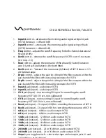
Freq:
The influ encing variables on this parameter will change the cu toff-
frequency. That is the frequency where the phase-shift at stage 6 is 180°. The
damp at this frequency will increase for higher stages. The controller
Freq
(3)
affects both filters and provides a range from 2 Hz to 42 kHz. By additional
external CV-voltage at
jack 11 resp. 12
the cutoff-frequency can be driven up
to 80 kHz. This cou ld be u sefu l to fu ll open the
VDL6
to get at stage 6
minimum damp at high audible frequencies or to get at stage 1of the
HDH6
maximum damp at lower frequencies. Vice versa relationships we get at corner
frequencies around 2 Hz or less (possible by additional negative CV-voltages)
to obtain maximum damp at stage 1 for the
VDL6
for higher frequencies or to
get minimum damp at stage 6 of the
HDH6
for lower frequ encies. For diode
filters the damping starts very early and affects the audio spectrum slowly
more and more. So, the damping curve is very smooth, different to typical de-
coupled 4-pol-filters. The controller
Det B (4)
(detune) only affects the cutoff-
frequency of VCF B and provides a detuning of about ±3.6 octaves (x12 resp.
÷12). The regarding control inputs for the cutoff-frequency are the jacks
CV A
for VCF A and
CV B
for VCF B with a sensitivity of about 2 octaves/volt resp. a
scale of about 0.5 V/oct.. These inputs are non-calibrated.
Reso:
The influ encing variables on this parameter will change the self-
resonance of the filters u p to self-oscillation. With increasing resonance the
filters become more and more selective around the cutoff-frequency and gain
the frequencies of the incoming audio at this point. The controller
Reso (5)
provides a range of no selectivity (
Reso
= 0) u p to self-oscillation (
Reso
> 7).
The regarding control jacks are
Res A
(13)
and
Res B (14)
. For a full sweep of
this parameter a voltage range ∆V of 5 volts is necessary. Depending on the
controllers' position
Reso
in one case -5 V are necessary to bring the resonance
back to zero for fu ll clockwise position and +5 V to achieve "10" for cou nter
clockwise position of
Reso
. The controller
Det B (6)
affects only VCF B and
"detunes" the resonance about ±1/3 of the full range.
Drp A, Drp B:
Many filters are bringing along to increasing resonance values a
concomitant damp of frequencies within the pass band. This gain loss or
drop
can be adju sted with the controllers
Drp A (7)
resp.
Drp B (8)
for the filters A
and B, separately, between -24 db and 0 db for
HDH6
and between -25 db and
0 db for
VDL6
. Fig. 4a illustrates the high-pass function, the resonance and the
drop for the
HDH6
whereas Fig. 4b shows that for the
VDL6
.
Содержание CS-8 ol HDH6
Страница 1: ...CS 8 Series ol Owners manual...
Страница 2: ......
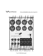
Страница 11: ...CS 8 ol HDH6 VDL6 Rev1 04 Feb 2015 Fig 1a HDH6 front panel...
Страница 12: ...CS 8 ol HDH6 VDL6 Rev1 04 Feb 2015 Fig 1b VDL6 front panel...