Chippmann CS-8 ol HDH6 Скачать руководство пользователя страница 15


CS-8 ol HDH6/VDL6 Rev1.04, Feb. 2015 


-13-

7.3 Initial operation 

 
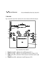
The  power  connector’s  (8)  pin-ou t  in  top  view  (refer  to  fig.  2)  is  assigned  as 
follows:  
Bottom to top, left to right. Thus pin 1 is located at bottom left, pin 2 above pin 
1 etc. Pin 15 is at bottom right, pin 16 at top right.  
 
Pin 1, 2   = -12 V (labeled with a triangle) 
Pin 3-8   = GND (regarding ground, 0 V), located outward on all jacks  
Pin 9, 10 = +12 V 
Pin 11-16 = not connected 
 
To  hook  u p  power  to  the  modu le,  connect  one  of  the  IDC-connector  of  the 
included flat ribbon cable to the box header (refer to fig. 2). Observe guide key 
for the polarity of the connector in order to avoid pin reversal. The red tag of 
the cable is to match the triangle-label. 
 

7.4 Calibration 

 
All  trimmers  are  12  gauge  trimmers,  i.  e.,  12  turns  are  needed  to  cover  the 
entire  range.  the  trimmers  P1,  P2,  P4  and  P5  increase  their  parameters  when 
turned  clockwise.  The  feed-through  trimmers  P3  und  P6  are  zero-adjustment 
trimmers and should better be untouched! 
 

Note:  This  is  a  complex  full  analogue  working  circuit,  where  scattered 
parts  will  heat  up  more  or  less.   Moreover  big  capacitors  with  large  time 
constants need time to charge. This causes to a so-called transient where 
the device achieves its final state.  
Clear text: "Frequency" and "Resonance" will drift more or less after a cold 
start and achieves after 3 minutes about 95% of the as last set values. 


Содержание CS-8 ol HDH6

Страница 1: ...CS 8 Series ol Owners manual...

Страница 2: ......

Страница 3: ...onic musical instruments is constantly striving for improvements and developments of their products Therefore we reserve the right to change technical specifications which improve our products at any...

Страница 4: ...ns a maximum slope of 36 db octave Accordingly to this VDL6 stands for Vertical Diode Low pass with also a slope of 36 db octave Each of these filters is contructed as a true dual filter containing tw...

Страница 5: ...4 2 CE AND FCC COMPLIANCE STATEMENTS 5 3 DISPOSAL 5 4 SAFETY INSTRUCTIONS 5 5 MAINTAINANCE CLEANING 6 6 GETTING STARTET 7 6 1 Unpacking 7 6 2 Installation 7 7 CONTROLS 8 7 1 Front panel 8 7 2 Backsid...

Страница 6: ...dealer s original invoice Final discretion of warranty coverage lies solely with Schippmann electronic musical instruments Any Schippmann electronic musical instruments product deemed eligible for rep...

Страница 7: ...tested and deemed to comply with the requirements listed in FCC Regulations part 15 The device complies with EN 55103 1 and EN 55103 2 standards Because of the entirely analogue construction this devi...

Страница 8: ...DUCT TO WATER BEER OR MOISTURE ADULTS ARE TO MAKE SURE THAT CHILDREN FOLLOW ALL SAFETY INSTRUCTIONS SAME THING GOES FOR PETS AVOID MECHANICAL STRESS OR IMPACT DO NOT DROP THE PRODUCT EVEN IF THERE IS...

Страница 9: ...ollowing items 1 x CS 8 ol HDH6 VDL6 3HU rack mount module 1 x Ribbon cable 20 cm length with two 16 pole IDC connectors 4 x M3 screws 4 x polypropylene washers This owners manual If the content of th...

Страница 10: ...CS 8 ol HDH6 VDL6 Rev1 04 Feb 2015 7 CONTROLS 7 1 Front panel Fig 1a and 1b shows the front panel with consecutively numbered controls and jacks for the modules HDH6 and VDL6...

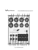
Страница 11: ...CS 8 ol HDH6 VDL6 Rev1 04 Feb 2015 Fig 1a HDH6 front panel...

Страница 12: ...CS 8 ol HDH6 VDL6 Rev1 04 Feb 2015 Fig 1b VDL6 front panel...

Страница 13: ...ithin the pass band of the filter with increasing resonance for VCF B 9 Input A jack input audio input VCF A 10 Input B jack input audio input VCF B 11 CV A jack input non inverting CV input for contr...

Страница 14: ...elements Fig 2 backside of the module 1 Freq A trimmer P1 calibration of cutoff frequency VCF A 2 Res A trimmer P2 calibration of starting point of self oscillation VCF A 3 FTR A trimmer P3 calibrati...

Страница 15: ...ty of the connector in order to avoid pin reversal The red tag of the cable is to match the triangle label 7 4 Calibration All trimmers are 12 gauge trimmers i e 12 turns are needed to cover the entir...

Страница 16: ...ge 5 Stage 6 Amp Amp Amp 6 db 12 db 18 db 24 36 db Slope Reso Input B VCF B Amp Stage 1 Stage 2 Stage 3 Stage 4 VCA Drp B Stage 5 Stage 6 Amp Amp Amp 6 db 12 db 18 db 24 36 db Slope Det B Freq Det B F...

Страница 17: ...VCF B and provides a detuning of about 3 6 octaves x12 resp 12 The regarding control inputs for the cutoff frequency are the jacks CV A for VCF A and CV B for VCF B with a sensitivity of about 2 octav...

Страница 18: ...6 high pass function resonance and drop level dB low pass function signal frequency emergence of a resonance peak level dB resonance drop gain loss signal frequency low pass function cutoff frequency...

Страница 19: ...6 12 18 36 6 12 18 36 slope db octave slope db octave Fig 5 HDH6 VDL6 slopes Note Subtracting of an output with a higher slope from one with a lower slope regardless whether within the same filter A...

Страница 20: ...typ 200 mA for each supplies 12 V Ambient temperature 0 C 55 C 7 32 F 131 F Net weight module only approx 200 g max dimensions W x H x D 19 PU 96 2 mm x 128 5 mm x 54 mm Installation depth behind the...

Отзывы: