02
NWC1 Series Self-healing Low Voltage Shunt Capacitors
and
heat
dissipation
of
the
capacitors
under
high
temperature
environment
and
keep
the
capacitors
away
from
heat
source
.
3
.
4
Transportation
conditions
:
The
capacitors
should
be
transported
within
original
package
(
packed
in
foam
box
).
The
product
should
be
handled
carefully
during
transportation
,
to
prevent
the
capacitor
body
from
deformation
due
to
collision
.
The
product
should
be
placed
on
upper
level
when
loaded
onto
the
truck
.
The
capacitor
assembly
must
be
placed
vertically
during
transportation
,
with
an
inclination
less
than
30
degrees
.
4
Key
Technical
Parameters
and
Performance
4
.
1
See
Table
2
for
key
technical
parameters
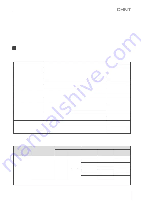
Table
2
Key
technical
parameters
Rate
voltage
(
kV
)
0
.
4
~
0
.
69
See
Table
3
Rate
capacity
(
kvar
)
5
~
100
See
Table
3
Rate
frequency
(
Hz
)
50
or
60
Default
50
Capacitance
deviation
(%)
-
5
~+
8
Short
circuit
discharge
before
test
Dissipation
factor
≤
30kvar
product
:
tan
δ≤
0
.
0012
>
30kvar
product
:
tan
δ≤
0
.
0015
Withstand
voltage
(
kV
)
Inter
-
pole
:
power
frequency
2
.
15U
N
,
2s
Pole
-
to
-
case
:
2
.
0
U
N
+
2
kV
or
3
kV
(
take
higher
),
5s
Maximum
allowable
overvoltage
1
.
1U
N
,
no
more
than
8h
of
continuous
operation
within
24h
Maximum
allowable
overcurrent
1
.
3I
N
,
no
more
than
2h
of
continuous
operation
within
24h
Short
time
≤
2
.
0IN
Self
-
discharge
characteristics
Residual
voltage
drops
from
√
2U
N
to
75V
(
DC
)
or
below
within
3min
after
power
off
.
Ambient
temperature
(℃)
-
25
~+
50
(-
25
/
C
)
Customizable
-
40
~+
50
Relative
temperature
≤
50
%
at
40
℃, ≤
90
%
at
20
℃
Altitude
(
m
)
≤
2000
Tightening
torque
(
N
?
m
)
M6
screw
≤
7
,
M8
screw
≤
10
Safety
protection
Self
-
healing
+
overpressure
protection
+
discharge
device
Short
circuit
discharge
before
test
Installation
method
Vertical
Note
:
Other
voltages
are
customizable
,
the
maximum
capacity
is
100kvar
.
4
.
2
See
Table
3
for
specifications
and
outline
dimensions
of
main
models
Table
3
Specifications
and
outline
dimensions
of
main
models
Qc
√
3U
N
Qc
U
N
Rated
current
I
N
(
A
)
3
-
three
phase
1
-
single
phase
Rated
voltage
U
N
(
kV
)
Optimal
capacity
Qc
(
kvar
)
Outline
and
installation
dimensions
Capacity
range
Height
H
Figure
number
0
.
4
,
0
.
415
,
0
.
45
,
0
.
525
,
0
.
69
5
,
7
.
5
,
8
,
10
,
15
,
16
,
18
,
20
,
25
,
30
,
40
,
50
,
60
,
80
,
100
1
~
10
160
Figure
1
12
~
16
220
Figure
1
18
~
20
260
Figure
1
22
~
30
230
Figure
2
32
~
40
270
Figure
2
45
~
60
300
Figure
3
80
~
100
300
Figure
4
Note
:
See
the
outline
and
installation
dimensions
in
this
manual
for
the
figure
number
of
outline
and
installation
dimension
drawings
.


