


14
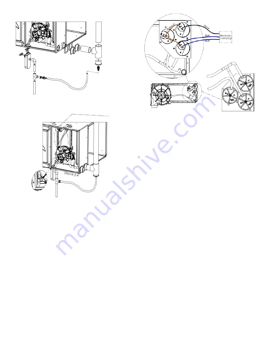
Figure 9 Horizontal right drain trap position
Figure 10 Horizontal right condensate tubing
4.4.2-
Horizontal right vent drainage
All furnace with horizontal exhaust vent piping must have a drain tee
assembly and trap installed in the exhaust pipe as close to the furnace as
possible (See Figure 10 Horizontal right condensate tubing).
4.4.3-
Condensate box pressure switch
The 3/16 stub just beside the drain of the condensate box must be drilled
or cut open. The PVC tubing of the pressure switch -0.2 (nearest to the ID
blower) must be connected to this stub.
The pressure switch needs now to be electrically connected in series with
the low fire pressure switch (top) with the brown jumper. See Figure 11
Pressure switch assembly and wiring diagrams.
Figure 11 Pressure switch assembly
4.5- HORIZONTAL LEFT ORIENTATION
4.5.1-
Horizontal left condensate drain connection
1.
Remove the knock-outs from the bottom middle side of the
casing.
2.
Drill open the bottom stub of the ID blower if not already open.
Be sure to remove all debris.
3.
Reroute the ID blower drain tube from the bottom of the ID blower
casing to one of the 1/2
” stub.
Do not screw the drain trap to
the furnace casing.
4.
Block the other open ID blower drain with a 1/2
’’ black cap.
5.
Reroute the condensate box drain tube from the bottom of the
condensate box through the casing.
6.
Reroute de vent collector drain tube to one of the 1/2
” stub.
7.
Apply the neoprene 7/8’’ gasket around the 5/8’’ and 1/2” tubes
at the point where they cross the furnace casing to seal the
passage.
8.
Plug the 5/8’’ and 1/2” tubes to the drain trap, securing the
connections with the clamps. The drain trap must be vertical.
9.
Connect the outlet drain from the drain trap to an additional
condensate piping in compliance with the local building codes; or
to a condensate pump approved for use with acidic furnace
condensate.
Содержание c105-1-d
Страница 20: ...20 Figure 16 Wiring diagram One stage PSC ...
Страница 21: ...21 Figure 17 Two Stage PSC Furnace Control ...
Страница 22: ...22 Figure 18 Two Stage ECM Furnace Control ...
Страница 26: ...26 Figure 21 Direct venting Figure 22 Multi venting ...
Страница 37: ...37 Figure 25 Part list 1 Stage PSC ...
Страница 38: ...38 Figure 26 Part list 1 Stage PSC continued ...
Страница 41: ...41 Figure 27 Part list 2 Stage PSC ...
Страница 42: ...42 Figure 28 Part list 2 stage PCS continued ...
Страница 45: ...45 Figure 29 Part list X13 ...
Страница 46: ...46 Figure 30 Part list X13 continued ...
Страница 49: ...49 Figure 31 Part list 2 Stage ECM ...
Страница 50: ...50 Figure 32 Part list 2 Stage ECM continued ...


