background image

Chinook 200 Nominal

Output Voltage

DC Fuse / DC Circuit Breaker Rating

12V

25 Amp

24V 

13 Amp

Run  / Stop Switch -

 A simple switch arrangement can provide a safe and easy way of stopping 

the turbine during high winds  or  for  maintenance.   A ‘SPDT’ (single pole double throw) switch is 
best for  this  purpose. As  the switch is  thrown, the batteries  are disconnected and  the turbine  is 
‘shorted’ reducing the rotor to a slow rotation. Refer to the generic wiring diagram.

Charge Controller -

  The 

Chinook 200

 diversion charge controller is  used to manage the power 

output  from the  turbine  to the  batteries. A diversion charge controller  operates  by  increasingly 
switching output to a dump load once the batteries  begin to reach high voltages. The dump load 
consumes  the ‘excess’ power  from  the turbine. This  means  that the turbine’s  power  output is  al-
ways  utilized whether  the batteries  are fully charged or not.  Depending on the size of the dump 
load, the turbine may slow down or stall  during a period when the power is  being diverted. Larger 
capacity battery banks will be able to store more energy and so the dump load will be used less.  

‘Hybrid’ Systems -

  The 

Chinook 200

 turbine can be used in parallel with PV panels. We recom-

mend  that the PV panels  are wired independently  with  a separate charge controller  specifically 
designed for  use with PV panels, and connected in parallel with the battery bank.   The Chinook 
200 controller can be used with PV Panels  as  long as  the Maximum  rated panel  output does  not 
exceed 

75 Watts 

when using the turbine’s dump controller.

User Manual   (Chinook 200) Rev D Final                                                                                                                                                           Page    14

Содержание 200

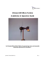
Страница 1: ...Chinook 200 Micro Turbine Installation Operation Guide 1m Diameter Micro Wind Turbine for generating clean and renewable electricity anywhere the wind blows User Manual Chinook 200 Rev D Final Page 1 ...

Страница 2: ... Introduction 4 Safety Precautions 5 Specifications 6 Package Contents 7 Assembly 8 Electrical Installation 13 Turbine Operation 16 Maintenance 17 Replacement Parts 18 Warranty 19 User Manual Chinook 200 Rev D Final Page 2 ...

Страница 3: ...trical power It must be installed in accordance with local building and electrical regulations Consult your local planning zoning office for details The Chinook 200 Micro Turbine has moving parts and Sharp Blades that may cause injury due to poor installation and unsafe handling or operation Chinook Turbines assumes no responsibility for problems caused by unsafe or unsatisfactory in stallation or...

Страница 4: ...sign Long life yaw pivot slip rings and wipers Easy tower top installation Simple design for low cost and durability The Chinook 200 is most at home in land based environments Thanks to its unique design the Chinook 200 is not susceptible to corrosion in normal operating conditions For Marine installs Please contact us for a Chinook 200 with Stainless Steel bearing option Applications include Remo...

Страница 5: ... This will prevent the turbine from spinning up during the installation Never install the turbine upside down or in any orientation other than that depicted on the installa tion instructions Install your turbine during a calm day When performing routine inspection or maintenance always stop the turbine by activating a stop switch or by shorting out the turbine output once disconnected from the bat...

Страница 6: ...ced Nylon Rotor Diameter 1 Meter 3 28 Feet Rated Wind Velocity 8m s 17 89 mph Rated Output 85 Watts Max Output 300 Watts Rated RPM 900 Start up Wind Velocity 3 5m s 7 8 mph Total weight 6 3 Kg 14 lbs Tower mount 1 5 Sch 40 Diameter pipe Chassis Construction Aluminium User Manual Chinook 200 Rev D Final Page 6 ...

Страница 7: ...onents shown below If any of the components are missing or damaged please contact your dealer immediately 3 Blades 1 Turbine Chassis 1 Controller 1 Spinner Nose Cone 1 Blade mounting plate Hardware Kit with allen wrenches and Manual User Manual Chinook 200 Rev D Final Page 7 ...

Страница 8: ...als to Break in and the lubrication to be distributed correctly around the bearing raceways and ball cages During this period you may notice a reduced performance caused by the additional friction of the bearing seals In operating temperatures of 10 degrees Centigrade or lower this Break in period will be extended by a further 50 hours of normal operation Connect a digital multi meter to the posit...

Страница 9: ...blades and rotor hub plate Be careful when handling the blades they may have sharp edges Use a 10mm socket hexagon key and three M6 x 16mm long cap screws to attach each blade to the hub plate The blades should all be fixed to the hub plate on the same side with the blades in the same orientation It is important that a washer is used underneath the Nylock nuts 3 set screws 3 washers and 3 Nylock n...

Страница 10: ...ssembly The assembled and balanced rotor blades can now be fitted to the Chi nook 200 chassis This is done by placing the rotor hub plate against the bearing house on the turbine In the hardware kit you will find 4 ea 5mm X 12 hex head screws NOTE you will have 3 ea 5mm X 14 hex head screws that are LONGER for use on the Nose cone Ensure that all 4 screws are securely tightened and that the rotor ...

Страница 11: ... When your tower or mount bracket is ready to have the turbine mounted the next stage is to run the wire from the top of the tower to where the electrical controller and batteries will be located Follow the table below to select the correct wire size This will vary depending on your nominal battery voltage and the distance that the cables will be run Careful selection of the wire size is required ...

Страница 12: ...one connect the tur bine output wires to the transmission wires using a terminal block with a minimum rating of 30 Amps Move the turbine up to the support structure and push the turbine body onto the tower Ensure that no wires are snagged Use the M6 x 70 fully threaded screw along with two washers and an Nylock nut to secure the turbine to the tower mount using the hole in the yaw pivot Ensure tha...

Страница 13: ...sion wires running down the tower from the turbine Clip the wires to the inside of the tower Failure to do this will result in excessive mechanical strain on the wire joints within the slip ring assembly and may cause a failure Wire ties or cable glands are a good way to prevent mechanical strain on the cables Negative Earth System The Chinook 200 turbine is based upon a negative earth system This...

Страница 14: ...egin to reach high voltages The dump load consumes the excess power from the turbine This means that the turbine s power output is al ways utilized whether the batteries are fully charged or not Depending on the size of the dump load the turbine may slow down or stall during a period when the power is being diverted Larger capacity battery banks will be able to store more energy and so the dump lo...

Страница 15: ...3 User Manual Chinook 200 Rev D Final Page 15 ...

Страница 16: ...h the tur bine output back to batteries Refer to the charge controller user manual for specific operational instructions Shut Down By activating the optional stop switch if you have installed one the output from the wires of the turbine are shorted together This effectively puts an infinite load on the generator causing the turbine to stall When the stop switch is activated the turbine may still r...

Страница 17: ...hinook Turbines for replacements Inspect the roots of the blades attachment tabs for signs of stress cracking or fatigue A new set of rotor blades should be installed if any cracks of fractures have occurred Remove any build up dirt and debris from the rotor blades using mild detergent in warm water Check the blade hub for excessive play Check and rebalance the rotor blades as required Check that ...

Страница 18: ...ler or Chinook Turbines for replacements Rotor Blades sold only in sets of 3 Slip Ring Wiper set of 2 Slip Ring sold only with yaw mount assembly Stator 24VDC Stator 12VDC Bridge Rectifier Yaw Bearing Housing Rotor Bearing Housing Turbine Controller Is programmed for specific voltage at the factory User Manual Chinook 200 Rev D Final Page 18 ...

Страница 19: ...enuine parts or from the use of liquid agents or lubricants in or on the turbine or control equipment Damage caused by operating the turbine in conditions outside of those specified in the Owners Guide including but not limited to allowing the turbine to run Un Loaded Damage caused by modifications to the turbine tower or control equipment not approved by Chi nook Turbines Damage caused to the tur...

Отзывы:

Похожие инструкции для 200