


Chapter 5
Useful Utilization (Optional)
CMN005-002
39
E
nglis
h
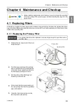
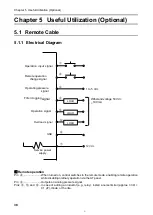
5.1.2
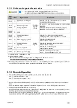
Color and signal of each wire
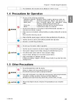
CAUTION
•
Do not short-circuit the wire [7] (yellow) with other wires.
A short-circuit may damage the AT panel and cause a malfunction.
Wire
Color
Pin#
Signal name
Description
Black
①
Operation input signal
*
1
Remote
signals
(
Input
)
With
④
and
⑧
short-circuited,
①
is short-
circuited to start operation.
Red/
White
④
Remote operation
change signal*
2
④
and
⑧
are short-circuited to start remote
operation.
Once this short circuit is established, ordinary
operation via the touch panel is disabled.*
3
Yellow/
White
⑧
GND
―
Black/
White
②
Operating pressure
signal *
2
Output
signals
Outputs the current operating pressure.
Analog signal: 1 to 5 V; impedance
4.7 kΩ
Red
③
Filter clogging signal *
2
Outputs a clogging signal.
Open collector output
Green
⑤
Operation output
signal *
2
Outputs an operation signal (ON lamp).
Open collector output
Green/
White
⑥
Overload signal
*
2
Outputs an overload signal.
Open collector output
Yellow
⑦
Service power supply
Outputs a service power supply.
12 Vdc,
Load Impedance (
≧
1 k
Ω
)
*1: Contact input Impedance
:
1.0
kΩ
*2: Open collector output
The maximum absolute rating is 50 V for voltage and 100 mA for current.
The recommended value is half or less of the rating.
*3
To change the performance level on the main unit while switching to remote operation, press and hold
the ON button on the main unit AT panel, and press the Lo or Hi button.
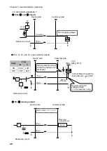
5.1.3
Remote Operation
•
For on/off switching via remote operation, short-circuit pins
④
and
⑧
.
Pin
①
is short-circuited
ON
Pin
①
is not short-circuited
OFF
•
Do not short-circuit between pins
④
and
⑧
when taking signals by on/off switching on the device
side.
Take out desired output signals as per the description in
•
Storing the performance level in the memory
By recording the performance level in the memory using the OFF button on the main panel, you can
start the operation at the stored performance level.
However, when the operation is stopped by turning off the main power switch, recall the performance
level stored with the OFF button by pressing the ON button once on the AT panel of the main unit.
Содержание SK-250AT
Страница 23: ...CMN005 003 21 6 3 3 SK 750AT PM ...
Страница 45: ...CMN005 002 43 6 3 3 SK 750AT PM ...
Страница 47: ...MEMO ...


