FWDIW Series
Installation Instructions
6
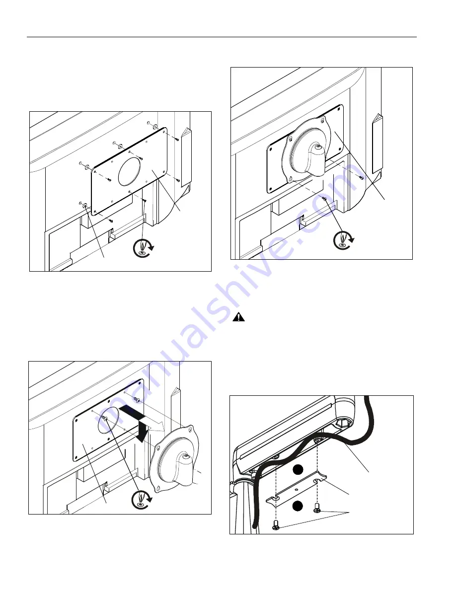
Attach Interface Bracket to Display
1.
Lay display face down on a clean and dry flat surface.
2.
Attach Interface Bracket (Q4) to display using six M4x16mm
Phillips flat machine screws (Q2) and six 1/8" spacers (Q3).
(See Figure 7)
3.
Tighten all screws.
Figure 7
Attach Display to Mount
1.
Start two M4 x 12mm Phillips pan head screws (R1) into top
mounting holes on interface bracket (Q4). (See Figure 8)
2.
Align two screws in interface bracket (Q4) with upper
mounting holes in Centris cup and lower display until
screws are seated in lower area of teardrop mounting
holes. (See Figure 8)
Figure 8
3.
Hold display so that display back is against Centris cup and
install two M4 x 12mm Phillips pan head machine screws
(R1) through lower mounting holes in Centris cup and into
lower mounting holes in interface bracket (Q4).
(See Figure 9)
Figure 9
Cable Management
1.
Attach all cables to display.
CAUTION:
Ensure that adequate cable slack exists for
movement of display, and that cables will not be pinched by
installation of cover (H) or screws (J).
2.
Carefully insert cables in cavity located in lower portion of
mount arm (See Figure 10).
3.
Using Phillips screwdriver, install cover (H) with two screws
(J). (See Figure 10)
Figure 10
(Q4)
(Q2) x 6
(Q3) x 6
(R1) x 4
(Q4)
(Q4)
(R1) x 4
(J) x 4
Cable Path
(typical)
(H) x 2
3
2


