MSP-WLK2
Installation Instructions
4
ASSEMBLY AND INSTALLATION
The MSP-WLK2 mounting arms are designed to be mounted to
MSP-WLC20 or MSP-WLC30 columns. These arms can be
used to create multiple display configurations as long as the
total weight capacity does not exceed the weight capacity of the
MSP-WLC20 or MSP-WLC30 that it is attached to.
1.
Install MSP-WLC20 or MSP-WLC30 column to mounting
surface following MSP-WLC20/30 installation instructions.
Do NOT install column cap until after the arms have been
installed.
2.
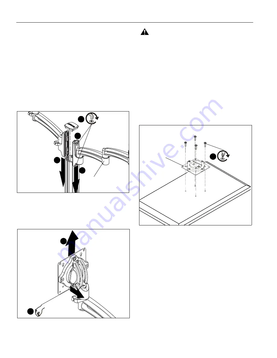
Slide MSP-WLK2 arm(s) (A) onto MSP-WLC20/30 column
in channels to be used for mounting. . (See Figure 1)
3.
Tighten screws to secure each arm to column at desired
mounting height. (See Figure 1)
4.
Replace cap on top of column. (See Figure 1)
Figure 1
Display Installation
1.
Remove quick release faceplate from mount by pulling
quick release lever and sliding faceplate off mount. (See
Figure 2)
Figure 2
WARNING:
Exceeding the weight capacity can result in
serious personal injury or damage to equipment! It is the
installer’s responsibility to make sure the combined weight of
all components attached to the MSP-WLK2 mount does not
exceed 25 lbs (11.34 lbs) per display. Use with products
heavier than the maximum weight indicated may result in
collapse of the mount and its accessories causing possible
injury.
2.
Carefully place display face down on protective surface.
3.
Connect faceplate to display
For flush mounting hole installation:
•
Using Phillips screwdriver, carefully install four
M4x10mm screws (B) through corresponding
holes on faceplate and into the mounting holes on
the display. (See Figure 3)
Figure 3
For recessed mounting hole installation:
•
Place four spacers (D) on top of mounting holes
on back of display. (See Figure 4)
•
Using Phillips screwdriver, carefully install four
M4x20mm screws (C) through corresponding
holes on faceplate, spacers (D) and into the
mounting holes on the display. (See Figure 4)
2
2
3
4
(A)
quick release lever
1
1
(for flush mounting holes)
(B) x 4
quick release
faceplate
3
Содержание Kontour MSP-WLK2
Страница 7: ...Installation Instructions MSP WLK2 7...


