Installation Instructions
JWP-210
4
INTRODUCTION
There are three main steps in the JWP-210
installation process. These steps are:
•
Selecting an appropriate mounting configuration.
•
Connect display cables
•
Making required adjustments
Before starting the installation process, determine the
correct mounting-hole configuration for your display by
reviewing the information located within Table 2.
NOTE:
If the displays mounting hole configuration does
not match those identified at right, a custom MSB
interface is required. Refer to a Chief Mfg. cross-
reference or visit
www.chiefmfg.com
to identify
the appropriate MSB for your display.
Reference Chart
Table 2 below provides a reference chart to help you
determine the mounting-hole configuration of your display
and quickly find the appropriate installation instructions.
Table 2. Installation Reference Chart
Screw Size
VESA Hole Pattern
Ref.
Page
M4 x 12mm
100mm x 100mm
(Flush Mount)
7
M4 x 20mm
100mm x 100mm
(Recess Mount)
7
M4 x 16mm
200mm x 100mm
8
M4 x 20mm
M6 x 20mm
M6 x 30mm
OR
M6 x45mm
200mm x 200mm
10
N/A
Non-VESA
(used with MSB Custom
Interface bracket, purchased
separately)
11
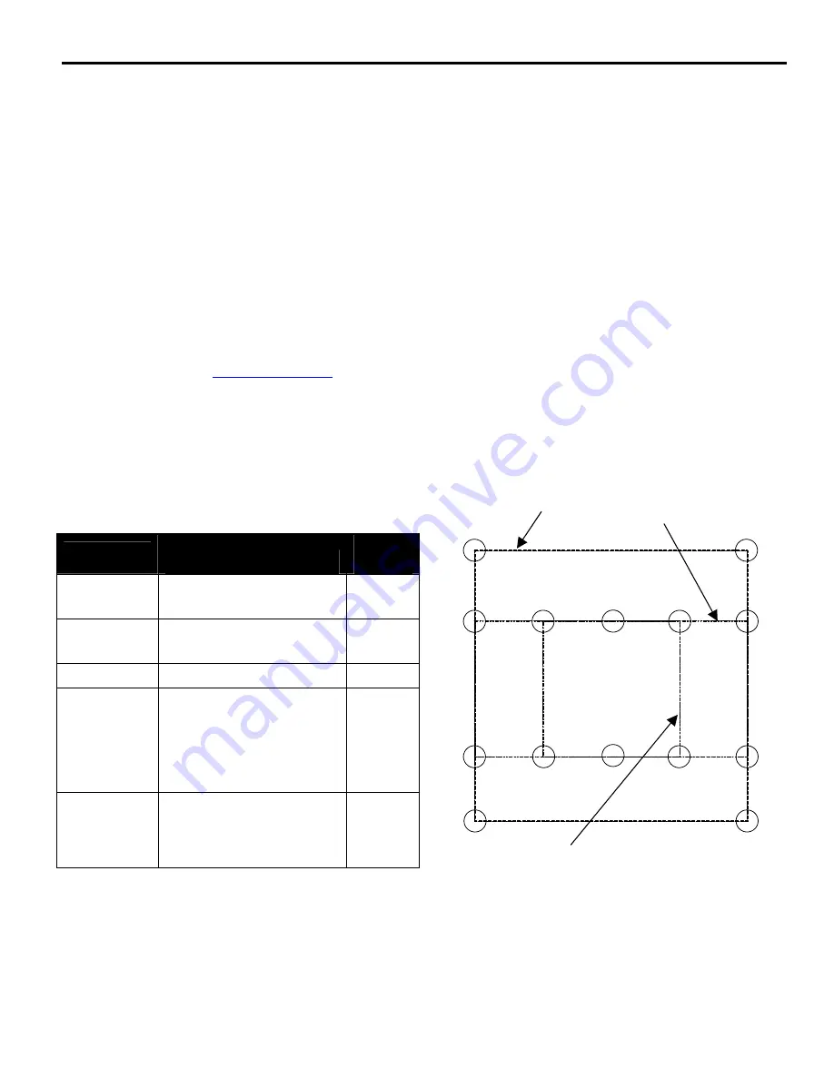
Mounting-Hole Configurations
Figure 1 depicts the various mounting-hole configurations
that are available to mount your display.
Figure 1.
Typical VESA Mounting Hole Configurations
100mm x 100mm
200mm x 100mm
200mm x 200mm


