EN
English
CP85030 / CP85050 / CP85080 / CP85100
Air Hydraulic jack
2. Machine type(s)
• An Air-Hydraulic jack is a device to lift a vehicle up to for accessibility during repair and maintenance.No other use permitted. For professional use only.
• A Jack is only a lifting device and should never be used for transporting and/or loading a vehicle. Lifting a vehicle with person inside is prohibited.
Moving the jack with load is prohibited.
• Please read the instructions carefully before starting the machine.
3. Mounting instruction
WARNING
Make sure every parts are fixed and tightened.
• First loosen the screw attached to the frame. (see fig. 01)
• Connect the hose and the spring to the lifting device. For 50000 kg, 80000 kg & 100000 kg jack, the white hose is connected to the left inlet, the Black
hose is connected to the right inlet.
• For 30000 kg jack, the white hose is connected to the right inlet, the black hose is connected to the left inlet. (see fig.02)
• To assemble the handle, see figure 03.
• To install the control lever, loosen the screw and rotate the control lever into the hole. (see fig.04)
• Do a complete cycle of lifting and lowering with no load, to purge air from the hydraulic system.
Document Ref: 8940169914_REV: 01 _ 05-2012
Scale: 1:1
Caution
Working area of 1 m must be kept free both in front of and behind the machine while it is in operation so that it is always
easily accessible.
4. Operation
• Verify the control lever is in the neutral position.
• Connect the shop air supply to the jack. Minimum air pressure is 8 bar for 30000 kg, 8.5 for 50000 kg, 9 bar for 80000 kg and100000 kg. Install an air
filter/lubricator in the shop air line, because water in the air line will damage the jack.
• Move the control lever clockwise to raise the saddle to the contact point. Move the control lever to neutral position.
• Check the placement of the jack. The load must be centered on the jack saddle. Avoid jack wheel obstructions such as gravel, tools, or uneven
expansion joints.
• Move the control lever clockwise to finish lifting the vehicle.
• Immediately place approved support stands under the vehicle’s lifting points (recommended by the vehicle manufacturer).
• To lower the load, move the control lever counter clockwise.
WARNING
• Brake vehicle. Chock vehicle tires that are still in contact with the ground.
• SLOWLY and CAREFULLY lower the vehicle onto the support stands by pushing the control lever counter
clockwise.
• It is not allowed to work under the raised load until it is secured by suitable means.
• The operator shall be provided with all necessary information about training and about pumping and translating
forces.
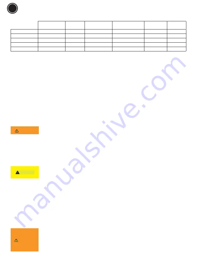
1. Technical Data (See figures 08, 09, 10 & 11)
Max. Lifting capacity
Pressure
Air Consumption
Hydraulic oil Quantity
ISO VG#15
Sound pressure
Weight
Unit
[kg] - [lb]
[bar]
[l/min] - [SCFM]
[l] - [oz]
dB
[kg] - [lb]
CP85030
30000 - 66138
8 - 12
10.5 - 0.37
0.9 - 30
70
38 - 83
CP85050
50000 - 110231
8.5 - 12
11.5 - 0.4
2.5 - 84
78
60 - 132
CP85080
80000 - 176369
9 - 12
11.5 - 0.4
6.2 - 209
77.8
103 - 227
CP85100
100000 - 220462
9 - 12
11.5 - 0.4
7.5 - 253
77.8
105 - 231
Static coefficient test: 1.5 / Dynamic Coefficient test: 1.2
All values are current as of the date of this publication. For the latest information please visit www.cp.com.
Declaration of noise and vibration statement
These declared values were obtained by laboratory type testing in accordance with the stated standards and are suitable for comparison with the
declared values of other tools tested in accordance with the same standards. These declared values are not adequate for use in risk assessments and
values measured in individual work places may be higher. The actual exposure values and risk of harm experienced by an individual user are unique and
depend upon the way the user works, the workpiece and the workstation design, as well upon the exposure time and the physical condition of the user.
We, CHICAGO PNEUMATIC TOOLS, cannot be held liable for the consequences of using the declared values, instead of values reflecting the actual
exposure, in an individual risk assessment in a work place situation over which we have no control. This tool may cause hand-arm vibration syndrome
if its use is not adequately managed. An EU guide to managing hand-arm vibration can be found at www. pneurop.eu/uploads/documents/pdf/PN3-02-
NV_Declaration_info_sheet_0111.pdf We recommend a programme of health surveillance to detect early symptoms which may relate to noise or vibration
exposure, so that management procedures can be modified to help prevent future impairment.
Содержание CP85030
Страница 2: ...Fig 01 Fig 02 30T 50T 80T 100T...
Страница 3: ...Fig 03 Fig 04...
Страница 4: ...Fig 05 06 OIL TYPE ISO VG 15...
Страница 6: ...Fig 07 Fig 08 CP85030...
Страница 7: ...Fig 09 Fig 10 CP85050 CP85080...
Страница 8: ......
Страница 15: ...NOTES...
Страница 16: ...www cp com...


