background image

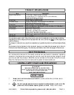
PRODUCT SPECIFICATIONS

SAVE THIS  MANUAL

You will need this manual for the safety warnings and precautions, assembly, operating,
inspection, maintenance and cleaning procedures, parts list and assembly diagram.  Keep
your invoice with this manual.  Write the invoice number on the inside of the front cover.
Keep this manual and invoice in a safe and dry place for future reference.

GENERAL SAFETY RULES AND PRECAUTIONS

WARNING!

READ AND UNDERSTAND ALL INSTRUCTIONS

Failure to follow all instructions listed below may result in

electric shock, fire, and/or serious injury.

SAVE THESE  INSTRUCTIONS

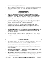
WORK AREA

1.

Keep your work area clean and well lit.  Cluttered benches and dark areas
invite accidents.

2.

Do not operate power tools in explosive atmospheres, such as in the
presence of flammable liquids, gases, or dust.  
Power tools create

SKU 95283         For technical questions, please call 1-800-444-3353        PAGE 2

The Emission Control System for this product’s engine is warranted for standards set by the U.S.
Environmental Protection Agency.  For warranty information, refer to the last pages of this manual.

This product requires a 50:1 ratio of fuel and 2-cycle oil to be added to its fuel tank before starting.
Attempting to start the Engine with an improper fuel mix, low or no fuel mix WILL ruin the Engine and
void the warranty.

The Engine’s Carburetor may need to be adjusted by a qualified mechanic for efficient high-altitude
use.

Item Description 

Engine Specifications 

1 HP / 26cc / Single Cylinder / 2-Stroke 
Fuel Required:  50:1 Unleaded Fuel & 2 Cycle Oil Mixture 
Fuel Tank Capacity:  0.2 Gallon 
Noise Level:  102 dB @ 3 Feet 

Drive Type 

Lever Operated Clutch System 

Chain/Bar Type 

Oregon Chain & Bar / Double Guard / Low Kickback 
3/8” Pitch with 39 Drive Link Count 

Chain Oiler 

Built Into Base of Chain Head Attachment 

Recommended Chain Oil 

S.A.E. 30 (Below 34° Fahrenheit) / S.A.E. 40 (Above 75° Fahrenheit ) 

Pole Height 

8 Feet (Including 10” Bar) 

Construction 

Main Poles:  Steel Tubing 
Chain Bar:  Stamped and Formed Steel 
Chain:  Machined High Carbon Steel 
Guards/Trim:  Multi-Colored High Impact Plastic 

Spark Plug 

NHSP L8RTF, Gap = 0.5~0.7mm (.0197~.0275inch) 

Net Weight 

12.13 Pounds 


®

Содержание 95283

Страница 1: ...ine with an improper fuel mix low or no fuel mix will permanently damage the unit CAUTION Your Warranty Is Voided If Copyright 2006 by Harbor Freight Tools All rights reserved No portion of this manual or any artwork contained herein may be reproduced in any shape or form without the express written consent of Harbor Freight Tools For technical questions please call 1 800 444 3353 GAS POWERED POLE...

Страница 2: ...tandards set by the U S Environmental Protection Agency For warranty information refer to the last pages of this manual This product requires a 50 1 ratio of fuel and 2 cycle oil to be added to its fuel tank before starting Attempting to start the Engine with an improper fuel mix low or no fuel mix WILL ruin the Engine and void the warranty The Engine s Carburetor may need to be adjusted by a qual...

Страница 3: ...rotating part of the machine may result in personal injury 5 Do not overreach Keep proper footing and balance at all times Proper footing and balance enables better control of the power tool in unexpected situations TOOL USE AND CARE 1 Do not force the tool Use the correct tool for your application The correct tool will do the job better and safer at the rate for which it is designed 2 Do not use ...

Страница 4: ...isk of electric shock or injury SPECIFIC SAFETY RULES AND PRECAUTIONS 1 IMPORTANT Your Warranty is voided if You do not operate the Polesaw Pruner with the proper 50 1 fuel mix in its fuel tank Never run the Engine with an improper fuel mix low or no fuel mix Running the Engine with an improper fuel mix low or no fuel mix will permanently damage the unit 2 Maintain labels and nameplates on the Pol...

Страница 5: ...e Polesaw Pruner 15 WARNING Stay clear of engine components which will be hot during and after operation KICKBACK PRECAUTIONS 1 Kickback is a dangerous reaction that can lead to serious injury Kickback may occur when the moving Chain contacts an object at the upper portion of the tip of the Guide Bar or when the wood closes in and pinches the Saw Chain in the cut Contact at the upper portion of th...

Страница 6: ...ate the Polesaw Pruner within 50 feet of any overhead electrical lines 2 NEVER use the Polesaw Pruner in damp or wet conditions CARBON MONIXIDE PRECAUTIONS 1 WARNING This Polesaw Pruner is designed for outdoor use only Do not operate the Polesaw Pruner in a closed area or in a poorly ventilated area When running the Engine of this product produces carbon monoxide a colorless odorless toxic gas tha...

Страница 7: ...nce or cleaning procedures always make sure the Power Switch is in its OFF position Allow the Engine to completely cool Then remove the spark plug from the Engine 2 Do not alter or adjust any part of the Polesaw Pruner or Engine that is assembled and supplied by the manufacturer 3 Always follow and complete scheduled Polesaw Pruner and Engine maintenance CHEMICAL PRECAUTIONS 1 Avoid contact with h...

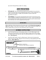
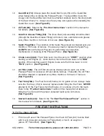
Страница 8: ...but must be supplied by the operator UNPACKING When unpacking check to make sure all the parts shown on the Parts Lists on pages 18 and 20 are included If any parts are missing or broken please call Harbor Freight Tools at the number shown on the cover of this manual as soon as possible ASSEMBLY INSTRUCTIONS 1 Insert the Gear Box 61 onto the upper section of the Top Pipe Support 33 Then secure the...

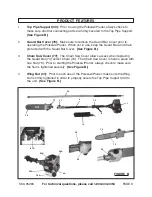
Страница 9: ...Guard Bar and Chain protected with the Guard Bar Cover See Figure B 3 Chain Saw Cover 77 The Chain Saw Cover allows access when replacing the Guard Bar 73 and or Chain 74 The Chain Saw Cover is held in place with one Nut 75 Prior to starting the Polesaw Pruner always check to make sure the Nut is tightened securely See Figure B 4 Wing Nut 31 Prior to each use of the Polesaw Pruner make sure the Wi...

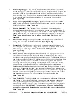
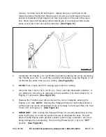
Страница 10: ...ts into the Bar Guard groove during tensioning Lift the tip of the Bar Guard up to check for sag Release the tip of the Bar Guard and turn the Chain Tensioning Screw 1 2 turn clockwise Repeat this process until sag does not exist Then retighten the Nut NOTE If the Chain is too tight it will not rotate Loosen the Nut slightly and turn the Chain Tension Adjusting Screw 1 4 turn counterclockwise Lift...

Страница 11: ... replaced every three months or 50 hours of tool use See Figure B 18 Fuel Tank 78A The Fuel Tank will hold up to 0 2 gallon of fuel Always make sure the Fuel Cap 74A is securely replaced after filling the Fuel Tank NEVER attempt to fill the Fuel Tank when the Engine 1 is running or hot to the touch Refer to the Pre Start Instructions section in this manual for full details on filling the Fuel Tank...

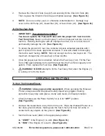
Страница 12: ...e unit Place the Polesaw Pruner on a flat level ground surface making sure the Saw Chain 74 does not come in contact with any objects on the ground See Figure B 4 Set the Choke Lever 48A to the appropriate position A START if the Engine 1 is cold See Figure B B RUN if the Engine 1 is warm See Figure B 3 NOTE Do not use dirty used or otherwise contaminated oil Damage may occur to the Oil Pump 47 Gu...

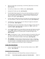
Страница 13: ...B 12 As soon as the Engine 1 is running check to make sure the Choke Lever 48A is in its RUN position Squeeze the Throttle Lever 8 briefly and let up The Throttle Lever will revert to its original position causing the Engine to idle See Figure B 13 NOTE If the Engine 1 is new or has been stored for a long period of time pull the Starter Handle 4A several times to ensure sufficient fuel is delivere...

Страница 14: ...or damage to the Guard Bar 73 Saw Chain 74 or Engine 1 See Figure B 6 IMPORTANT After running the Polesaw Pruner for an extended period of time allow the Engine 1 to idle for several minutes to dissipate the heat This will prevent some Engine parts ignition system piston rings carburetor etc from being damaged by overheating Then turn the Power Switch 10 to its OFF position See Figure B 2 Accelera...

Страница 15: ... Filter should be checked prior to each use of the Polesaw Pruner for excessive dirt and debris build up Thereafter the Air Filter should be cleaned or replaced every three months or 50 hours of tool use 6 Drive Gear 44 maintenance The Drive Gear assembly should be filled through the Gear Box Grease Fitting 50 with clean new automotive axle grease every three months or 50 hours of tool use 7 Befor...

Страница 16: ...STUD GUARD BAR 73 GUARD BAR STUD SLOT CHAIN TENSIONING PIN HOLES NUT 75 DRIVE GEAR 44 CHAIN 74 CHAIN ROTATION FIGURE C 1 2 3 4 SKU 95283 For technical questions please call 1 800 444 3353 PAGE 16 9 CAUTION All maintenance service or repairs not mentioned in this manual must only be performed by a qualified service technician 8 When storing the Polesaw Pruner Before storing make sure to install the...

Страница 17: ...ER INSTALLATION OF REPLACEMENT PARTSTHERETO TROUBLESHOOTING Problem Possible Cause Possible Solution Guard Bar and Chain running hot and smoking 1 Chain tension too tight 2 Chain Oil Tank empty 1 Re adjust Chain Tension Adjusting Screw to lesson tension on Chain 2 Refill Chain Oil Tank Engine runs but Chain is not rotating 1 Chain tension too tight 2 Damaged Guard Bar and or Chain 1 Re adjust Chai...

Страница 18: ...5 Drive Gear 14 Shoulder Harness 56 Washer 15 Screw 57 Spring Washer 16 Nut 58 Screw 17 Transmission Cover 59 Screw 18 Bearing 60 Washer 19 Socket Head Bolt 61 Gear Box 20 Pipe Cover 62 Screw 21 Orientation Block 63 Spring Washer 22 Connector 64 Washer 23 Spring 65 Sprocket 24 Washer 66 Washer 25 Spring Washer 67 Chain Oil Tank Cap 26 Screw 68 Ventilator 27 Washer 69 Chain Oil Tank 28 Screw 70 Spr...

Страница 19: ...stions please call 1 800 444 3353 PAGE 19 ASSEMBLY DIAGRAM POLESAW PRUNER UNIT NOTE Some parts are listed and shown for illustration purposes only and are not available individually as replacement parts 83 Hex Wrenches not shown ...

Страница 20: ...9A Piston 16A Ball Bearing 60A Piston Pin Ring Snap 17A Crankcase 61A Crankshaft Assy 18A Front Crankcase 62A Needle Bearing 19A Flywheel 63A Piston Pin 20A Centrifugal Clutch 64A Piston Pin Ring Snap 21A Clutch Spring 65A Woodruff Key 22A Ripple Washer 66A Screw Set 23A Clutch Screw 67A Muffler Gasket 24A Clutch Drum 68A Baffle 25A Bearing 69A Muffler 26A Block 70A Inner Hex Bolt 27A Switch Wires...

Страница 21: ...A 61A 62A 63A 64A 84A 12A 13A 14A 15A 16A 71A 71A 72A 73A 1A 2A 3A 4A 5A 6A 7A 8A 9A 10A 11A 83A 70A 69A 67A 66A 68A 74A 75A 76A 77A 78A 79A 83A 80A 81A 82A 65A 17A 18A 19A 20A 21A 85A 22A 23A 24A 25A 26A 28A 27A 29A 30A 31A 32A 33A 39A 34A 35A 38A 36A 37A NOTE Some parts are listed and shown for illustration purposes only and are not available individually as replacement parts ...

Страница 22: ...are responsible for shipping your engine to a HFT warranty station as soon as a problem exists Contact the HFT Customer Service department at the number below to make shipping arrangements The warranty repairs should be completed in a reasonable amount of time not to exceed 30 days If you have any questions regarding your warranty rights and responsibilities you should contact the Harbor Freight T...

Страница 23: ... from date of purchase that the motor the belts if so equipped and the blades if so equipped are free of defects in materials and workmanship Harbor Freight Tools also warrants to the original purchaser for a period of one year from date of purchase that all other parts and components of the product are free from defects in materials and workmanship This warranty does not apply to damage due direc...

Отзывы: