background image

Page 8

For technical questions, please call 1-800-444-3353.

SKU 68394

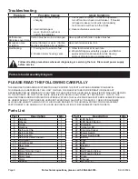
Troubleshooting

Problem

Possible Causes

Likely Solutions

Tool will not start.

1.  No power at outlet during 

charging. 


2.  Internal damage or 

wear.  (Carbon brushes or 

switch, for example.)

1.  Check power at outlet.  If outlet is unpowered, 

turn off tool and check circuit breaker.  If breaker 

is tripped, make sure circuit is right capacity 

for tool and circuit has no other loads.

2.  Have technician service tool.

Performance 

decreases over time.

Carbon brushes worn or damaged. Have qualified technician replace brushes.

Excessive noise 

or rattling.

Internal damage or wear.  (Carbon 

brushes or bearings, for example.)

Have technician service tool.

Overheating.

1.  Forcing tool to work too fast. 

2.  Blocked motor housing vents.

1.  Allow tool to work at its own rate.
2.  Wear ANSI-approved safety goggles and NIOSH-

approved dust mask/respirator while blowing 

dust out of motor using compressed air.

  Follow all safety precautions whenever diagnosing or servicing the tool.  Disconnect power supply 

before service.

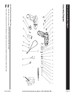
Parts List and Assembly Diagram

PLEASE READ THE FOLLOWING CAREFULLY

THE MANUFACTURER AND/OR DISTRIBUTOR HAS PROVIDED THE PARTS LIST AND ASSEMBLY DIAGRAM IN 

THIS MANUAL AS A REFERENCE TOOL ONLY.  NEITHER THE MANUFACTURER OR DISTRIBUTOR MAKES ANY 

REPRESENTATION OR WARRANTY OF ANY KIND TO THE BUYER THAT HE OR SHE IS QUALIFIED TO MAKE ANY REPAIRS 

TO THE PRODUCT, OR THAT HE OR SHE IS QUALIFIED TO REPLACE ANY PARTS OF THE PRODUCT.  IN FACT, THE 

MANUFACTURER AND/OR DISTRIBUTOR EXPRESSLY STATES THAT ALL REPAIRS AND PARTS REPLACEMENTS SHOULD 

BE UNDERTAKEN BY CERTIFIED AND LICENSED TECHNICIANS, AND NOT BY THE BUYER.  THE BUYER ASSUMES 

ALL RISK AND LIABILITY ARISING OUT OF HIS OR HER REPAIRS TO THE ORIGINAL PRODUCT OR REPLACEMENT 
PARTS THERETO, OR ARISING OUT OF HIS OR HER INSTALLATION OF REPLACEMENT PARTS THERETO.

Parts List

Part

Description

Qty.

1

Spindle

1

2

Washer

1

3

C-Clip

1

4

Gearbox

1

5

Self-Lock Chip

1

6

Self-Lock Ring

1

7

Self-Lock Pin

1

8

Self-Lock Center Bracket

1

9

Front Gear

3

10

Cnter Bracket

1

11

Rear Gear

3

12

Gasket

1

13

Motor Terminal Cover

1

14

Motor Screw

2

15

Motor Gear

1

16

Motor

1

17

Housing

1 set

Part

Description

Qty.

18

LED Button

1

19

LED Switch Spring

1

20

PCB LEB

1

21

Indicator LED

1

22

Charging Socket

1

23

Power Switch

1

24

Power Switch PCB

1

25

Battery

1

26

Lens

1

27

LED

1

28

Resistor

1

29

Belt

1

30

Self-Tapping Screw

5

31

Self-Tapping Screw

4

32

Clasp

1

33

Charger

1

34

Bit (PH2, 2”)

1

Содержание 68394

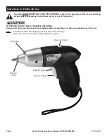
Страница 1: ...oon as possible Visit our website at http www harborfreight com Copyright 2011 by Harbor Freight Tools All rights reserved No portion of this manual or any artwork contained herein may be reproduced in any shape or form without the express written consent of Harbor Freight Tools Diagrams within this manual may not be drawn proportionally Due to continuing improvements actual product may differ sli...

Страница 2: ...ed could result in death or serious injury CAUTION used with the safety alert symbol indicates a hazardous situation which if not avoided could result in minor or moderate injury NOTICE is used to address practices not related to personal injury CAUTION without the safety alert symbol is used to address practices not related to personal injury General Power Tool Safety Warnings WARNING Read all sa...

Страница 3: ...ore making any adjustments changing accessories or storing power tools Such preventive safety measures reduce the risk of starting the power tool accidentally d Store idle power tools out of the reach of children and do not allow persons unfamiliar with the power tool or these instructions to operate the power tool Power tools are dangerous in the hands of untrained users e Maintain power tools Ch...

Страница 4: ...s or other reproductive harm Wash hands after handling California Health Safety Code 25249 5 et seq 11 The warnings precautions and instructions discussed in this instruction manual cannot cover all possible conditions and situations that may occur It must be understood by the operator that common sense and caution are factors which cannot be built into this product but must be supplied by the ope...

Страница 5: ...ouble insulation system which satisfies OSHA requirements and complies with the applicable standards of Underwriters Laboratories Inc the Canadian Standard Association and the National Electrical Code 2 Double insulated tools may be used in either of the 120 volt outlets shown in the preceding illustration See Outlets for 2 Prong Plug Extension Cords Note Extension cords must not be used with this...

Страница 6: ...ubheadings therein before set up or use of this product TO PREVENT INJURY FROM ACCIDENTAL OPERATION Release the Trigger and disconnect Power Adapter before assembling or making any adjustments to the tool Note For additional information regarding the parts listed in the following pages refer to Parts List and Assembly Diagram on page 11 Magnetic Chuck Work Light Switch Work Light Forward Trigger R...

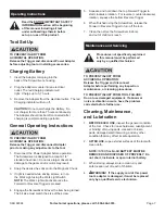
Страница 7: ...rk Light will activate once the Forward or Reverse Trigger is pressed 4 Engage the Screwdriver bit over the item being turned The bit size must match the size of the screw 5 Squeeze and hold down the top Forward Trigger to start clockwise rotation For reverse counterclockwise rotation squeeze the bottom Reverse Trigger 6 When finished using the Screwdriver release the Forward Reverse Trigger to tu...

Страница 8: ...ND OR DISTRIBUTOR HAS PROVIDED THE PARTS LIST AND ASSEMBLY DIAGRAM IN THIS MANUAL AS A REFERENCE TOOL ONLY NEITHER THE MANUFACTURER OR DISTRIBUTOR MAKES ANY REPRESENTATION OR WARRANTY OF ANY KIND TO THE BUYER THAT HE OR SHE IS QUALIFIED TO MAKE ANY REPAIRS TO THE PRODUCT OR THAT HE OR SHE IS QUALIFIED TO REPLACE ANY PARTS OF THE PRODUCT IN FACT THE MANUFACTURER AND OR DISTRIBUTOR EXPRESSLY STATES ...

Страница 9: ...1 23 24 25 26 27 28 29 30 31 32 Record Product s Serial Number Here Note If product has no serial number record month and year of purchase instead Note Some parts are listed and shown for illustration purposes only and are not available individually as replacement parts 33 34 Parts List and Assembly Diagram Assembly Diagram ...

Страница 10: ...al damages so the above limitation of exclusion may not apply to you THIS WARRANTY IS EXPRESSLY IN LIEU OF ALL OTHER WARRANTIES EXPRESS OR IMPLIED INCLUDING THE WARRANTIES OF MERCHANTABILITY AND FITNESS To take advantage of this warranty the product or part must be returned to us with transportation charges prepaid Proof of purchase date and an explanation of the complaint must accompany the merch...

Отзывы: