26
Always check that the arrow of the current sensor points towards the load. This ensures that the phase angle will be correct for
power measurements and other measurements that depend on the phase.
However, when a recording session has ended and been uploaded to a PC, it is possible to change the direction of the current (I1,
I2, or I3) using the PEL Transfer software. This makes it possible to correct the power calculations.
4.1.1. SINGLE-PHASE, 2-WIRE: 1P-2W
Source
Load
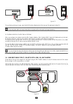
For Single-Phase 2-Wire measurements:
Connect the N test lead to the neutral conductor
Connect the V1 test lead to the L1 phase conductor
Connect the I1 current probe to the L1 phase conductor.
Check that the current arrow on the sensor points towards the load.
This ensures proper phase angle for Power Measurements and other
phase-sensitive measurements.
N
L1
V1 V2 V3 N
I1
I2
I3
Figure 19
4.1.2.
DUAL-PHASE (SINGLE-PHASE 3-WIRE FROM A CENTER TAP TRANSFORMER): 1P-3W
For Single-Phase 3-Wire (Split Phase) measurements:
Connect the N test lead to the Neutral conductor
Connect the V1 test lead to the L1 phase conductor
Connect the V2 test lead to the L2 phase conductor
Connect the I1 current probe to the L1 phase conductor.
Connect the I2 current probe to the L2 phase conductor
Check that the current arrow on the sensor points towards the load.
This ensures proper phase angle for Power Measurements and other
phase-sensitive measurements.
N
L1
L2
L2
L1
N
V1 V2 V3 N
I1
I2
I3
Figure 20
4. USE
When the instrument has been configured, you can use it.
4.1. DISTRIBUTION NETWORKS AND CONNECTIONS OF THE PEL
Start by connecting the current sensors and the voltage measurement leads to your installation according to the type of distribution
network. The PEL must be configured (see § 3.4) for the distribution network selected.
Содержание pel 102
Страница 1: ...Power energy logger EN User s manual PEL 102 PEL 103 PEL 104 ...
Страница 24: ...24 Aggregation period Date and time IP address scrolling Wi Fi address scrolling PEL104 ...
Страница 34: ...34 Two phase 3 wire 2P 3W V1 V2 U12 VN P Q S PF P Q S tan ϕ ϕ V2 V1 ϕ I1 V1 ϕ I2 V2 I1 I2 f ϕ I2 I1 ...
Страница 36: ...36 Three phase 3 wire balanced 3P 3W b U12 U23 U31 f P Q S PF P Q S tan ϕ I1 I2 I3 ϕ I1 U12 ...
Страница 38: ...38 Three phase 4 wire wye balanced 3P 4WYb I1 I2 I3 V1 V2 V3 VN U12 U23 U31 f P Q S tan ϕ ...
Страница 39: ...39 DC 2 wire dC 2W DC 3 wire dC 3W P Q S PF ϕ I1 V1 P Q S tan ϕ P I V VN I1 I2 IN ...
Страница 40: ...40 DC 4 wire dC 4W P I1 I2 I3 IN V1 V2 V3 VN V1 V2 VN ...
Страница 48: ...48 Two phase 3 wire 1P 3W I1 I2 V1 V2 U12 VN P Q S P Q S ...
Страница 49: ...49 Three phase 3 wire 3P 3W 2 3P 3W 3 3P 3WO2 3P 3WO3 3P 3WY2 3P 3WY3 3P 3W b I1 I2 I3 U12 U23 U31 P Q S P Q S ...
Страница 51: ...51 P Q S ...
Страница 85: ...85 ...


