


Section 360-880-202
13
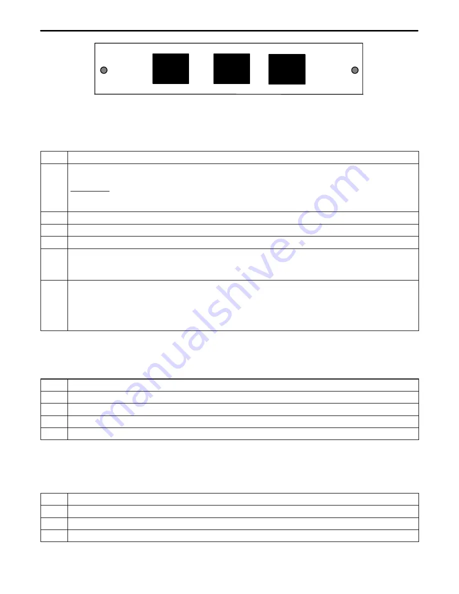
J6
J5
J4
+
+
SEC T1/EAST
T1CU
PRI T1/WEST
Figure 15. 3608-80 ST1U Rear Panel
5.1.2. Installing a New Unit
Use the following steps to install the ST1U.
Step
Action
1.
If not already installed, install the rear panel, screwing it to the appropriate mounting locations on the
shelf using the provided hardware.
WARNING: If there is already a rear panel installed on the shelf, check for interference when
mounting. The rear panel may need to be removed and replaced with the rear panel that has
been shipped with the new unit.
2.
Insert the unit into the shelf, making sure that the unit is aligned with the card guides inside the shelf.
3.
Slide the unit fully into the shelf. Use the insertion lever to fully seat the unit.
4.
Once the unit is fully inserted, tighten the securing screw on the front panel of the unit.
5.
Wire the unit per the wiring information in the wiring section.
When power is applied, the unit will perform a self-test to ensure that it is compatible with the network
management software on the system.
6.
After the self-test is performed, check the software provisioning of the unit using either the front panel
craft interface on the front of the controller unit or the network management interface on the rear of the
controller (see the section on network management for more information on this interface).
Note:
If a Secondary T1 unit is inserted into a shelf while power to the shelf is on, the T1 controller
unit may reset.
5.1.3. Installing a Replacement Unit
If you are replacing a unit that is already in service, insure that the new unit is the same as the unit being re-
placed.
Step
Action
1.
Remove the wiring connectors from the front and rear of the unit (J4, J5 & J6).
2.
Unscrew the front panel securing screw to release the unit from the shelf.
3.
Using the card ejector, remove the unit from the shelf.
4.
Follow the procedure for installing a new unit.
5.2
Wiring the Unit
5.2.1. Drop and Re-Insert Application
Use the following steps to wire the unit (see Figure 16).
Step
Action
1.
Connect the T1 from the WEST 360-80 ICB or equivalent to J6 of the ST1U.
2.
Using the cable provided with the unit, connect J5 to J1 on the T1-S.
3.
Connect J4 of the ST1U to the input of the next 360-80 ICB or to the EAST 360-80 ICB or equivalent.


