background image

Page 13 


3.


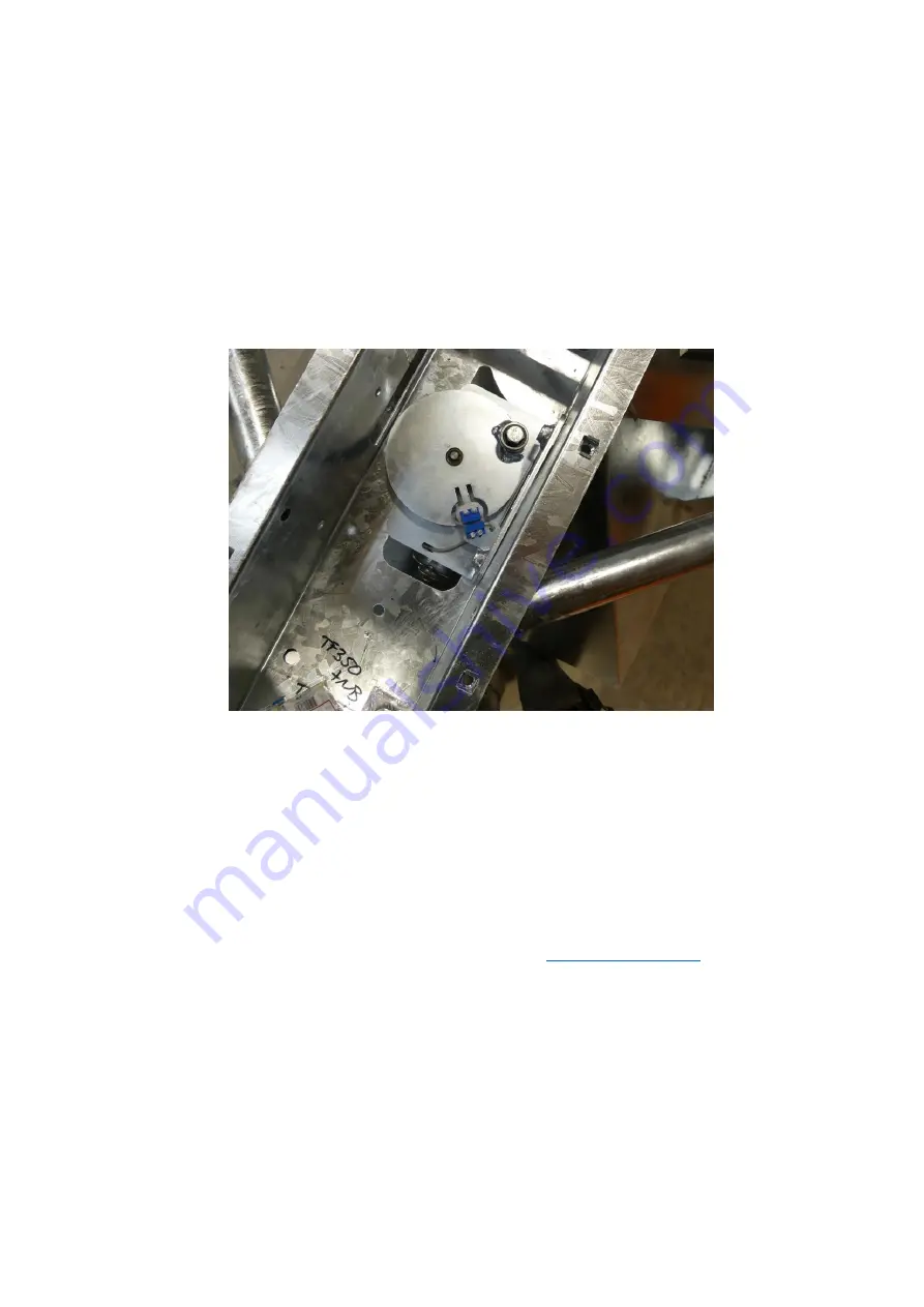
In the Picture below you can see the sensor (with the wire) and the magnet (fitted to the disc) are facing each 
other with approximately 2mm gap between them. The sensors also need to be aligned vertically (so that they 
are approximately level with each other). 

If required you can bend the sensor support bracket up or down to get vertical alignment, and you can move 
the sensor in or out on the slotted holes to get horizontal alignment. 
FOR MACHINES USED WITH DUSTY FEED OR FEED WITH ADDITIVES SUCH AS MOLLASES, BUILD UP OF DIRT 
CAN AFFECT THE SENSOR OPERATION 

 IN THIS CASE CLEAN WITH A LOW-PRESSURE WATER JET. 

 
Consult the relevant parts diagram for the sensor part number if spares are required, alternatively contact 
your distributor. 


4.


Parts are re-fitted as a reverse of removal, taking care to ensure all bolts are secure and tight. If adjustments 
have been made to the sensor, ensure the cable is secured with cable ties or similar to prevent accidental 
damage. 


Once this has been checked and all dirt removed, your problem should be resolved.  
If the problem persists, please contact us 01288 308 149 or email us on 

[email protected]

 and we will be more 

than happy to help. 

Содержание MF350

Страница 1: ...MF350 Mounted Feeder Original Instructions Chapman Machinery Ltd Hele Barton Week St Mary Holsworthy Devon EX22 6XR Tel 01288 308149 Email sales chapman co uk ...

Страница 2: ...eed 11 General Troubleshooting 14 Storage 14 Warranty 15 EC DECLARATION OF CONFORMITY 16 THIS MANUAL MUST BE HANDED TO THE OPERATOR BEFORE USE THE OPERATOR MUST UNDERSTAND FULLY THE CONTENT OF THIS HANDBOOK BEFORE USING THE MACHINE FOR THE FIRST TIME OF THE IMPLEMENT IS RESOLD THIS MANUAL MUST ACCOMPANY THE MACHINE NOTE The information contained in this manual is correct at the time of going to pr...

Страница 3: ...eyes from insects and branches with either a visor or goggles Trailed equipment and loads Ensure all riders know the manufacturers recommended towing capacity and drawbar loading limit Always operate within these requirements Remember that your ability to control the ATV by your body movements will be considerably reduced when carrying a load or towing a trailer When selecting trailed equipment lo...

Страница 4: ...t repairs Before starting carry out a visual check on both machine towing vehicle as regards functionality road safety accident prevention rules Even when using the machine correctly accidents can occur It is imperative that nobody stand within the danger area If working near roads buildings or animals special attention must be taken to ensure safety Never wear loose clothing which could get caugh...

Страница 5: ...alvanised metal hopper and PVC cover Please ensure the carrying vehicle has sufficient capacity for the base machine weight circa 90kg the weight of feed in the hopper when full These machines should however only be used to perform tasks for which they were designed use of the machine for any other function may be both dangerous to persons and potentially damaging to components Use of the machine ...

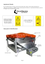
Страница 6: ...s before use Note All decals must be present and visible It is imperative that these are replaced if damaged to prevent potential harm to users Carefully read operators manual before handling this machine Observe instructions and safety rules when operating Caution Entanglement Hazard Keep hands away from moving parts Component Identification ...

Страница 7: ...d moisture Attaching the Machine NOTE This machine is designed to attach to the carrying vehicle using 4 x ratchet straps Never use less than 4 straps to secure the load as movement may result 1 Remove tailgate from carrying vehicle 2 Load MF350 into bed using forklift slots or suitable lifting strops rated to carry plated unladen weight If fitting for the first time and the hopper has been shippe...

Страница 8: ...esigned to be hard wired direct to the battery of the vehicle with a dedicated feed It is recommended that the control unit be hard wired into the vehicle to ensure cables do not get snagged and damaged by tools equipment dogs etc should the hopper need to be removed at a later stage the plug can be disconnected from the hopper and the control module can remain in the vehicle when not in use 6 Cal...

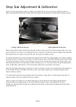
Страница 9: ... when heading out to feed or alternatively you can on first use measure the feed in the hopper before and after feeding to ensure the correct amount of feed is being put out It is not recommended to use this feeder with sticky feedstuff eg home blends or those containing molasses which can bridge in the hopper Adjust the feed adjustment plate as required to increase or decrease the drop size check...

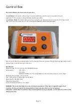
Страница 10: ...r the two flaps on the left and right of the unit Specification Supply Voltage 12V DC nominal 16V MAXIMUM Power Consumption OFF 0 01A ON 0 05A MOTOR RUNNING 5A If at all possible wire direct to battery due to current draw Operating Temperature 10 C to 40 C Fuse Thermal Reset Polyfuse Non serviceable Operating life 100 000 cycles Protection rating IP67 Incorrect polarity protection Yes diode WARNIN...

Страница 11: ... Fault No output is being received from sensor Check plug socket for dirt or corrosion preventing contact Check sensor for damage or corrosion The unit will continue to operate with this fault but will not count To exit this fault condition once the problem has been identified turn the unit off Operating Limits Recommendations Ensure that the operator is suitably qualified to use a machine of this...

Страница 12: ...7 Motor Red 3 Motor Green 5 Sensor Brown Cable White 1 Sensor White Cable If the connectors are functioning correctly then the unit may need adjustment of the sensor and magnet located within the machine Procedure 1 Remove the belly pan in order to access the running gear You may find it easier to remove the entire metering assembly from the hopper so that the unit can be worked on easier The mete...

Страница 13: ...H ADDITIVES SUCH AS MOLLASES BUILD UP OF DIRT CAN AFFECT THE SENSOR OPERATION IN THIS CASE CLEAN WITH A LOW PRESSURE WATER JET Consult the relevant parts diagram for the sensor part number if spares are required alternatively contact your distributor 4 Parts are re fitted as a reverse of removal taking care to ensure all bolts are secure and tight If adjustments have been made to the sensor ensure...

Страница 14: ...or No material is fed Jammed slide plate Check for blockages and remove Hopper bridging Agitate hopper contents Drop size varies Drop adjustment plate loose Adjust and tighten hand screws Feed leaking out from chute Jammed slide plate Check for blockages and remove Slide plate sticking May be ap parent on feeds with high molasses binding content Clean slide plate area A stronger return spring can ...

Страница 15: ...materials or equipment not manufactured by Chapman Machinery for which the Buyer shall only be entitled to the benefit of any such warranty or guarantee given by themanufacturer to Chapman Machinery Only genuine replacement parts will be allowable for warranty claims 7 All parts replaced by Chapman Machinery under warranty become the property of Chapman Machinery and must be returned to Chapman Ma...

Страница 16: ...m Name of Representative James Chapman Position of representative Director The Basis on which Conformity is being Declared I declare that as the authorised representative the above information in relation to the supply manufacture of this product is in conformity with the stated standards and other related documents following the provisions of Machinery Directive 2006 42 EC directives The products...

Отзывы: