background image

100899 - 2500W DUAL FUEL INvERTER GENERATOR

OPERATION

21

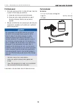
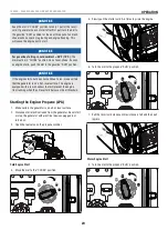
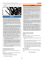
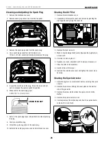
5.  Pull the recoil cord slowly until resistance is felt and then pull 

rapidly.


NOTICE

Accumulation of frost on LPG cylinder and regulators is 
common during operation and normally is not an indication 
of a problem. As LPG vaporizes and travels from the cylinder 
to the generator engine it expands. The amount of frost that 
forms can be affected by the size of the cylinder, the amount 
of LPG being used, the humidity of the air and other operating 
conditions.

In unusual situations this frost may eventually restrict the flow 
of LPG to the generator resulting in deteriorating performance. 
For example, if the cylinder temperature is reduced to a very 
low level then the rate at which the LPG vaporizes is also 
reduced and may not provide sufficient flow to the engine. This 
is not an indication of a problem with the generator but only 
a problem with the flow of LPG from the cylinder. If generator 
performance seems to be deteriorating at the same time that 
ice formation is observed on tank valve, hose or regulator then 
some actions may be taken to eliminate this symptom.

In these rare situations it can be helpful to reduce or eliminate 
the cold fuel system effects by doing one of the following:


Exchanging fuel cylinders to allow the first cylinder to 
warm up, repeating as necessary.


Placing the cylinder at the end of the generator near the 
handle, where engine fan air flows out from the generator. 
This air is slightly heated by flowing over the engine. The 
cylinder should not be placed in the path of the muffler 
outlet.


The cylinder can be temporarily warmed by pouring warm 
water over the top of the cylinder.

Connecting Electrical Loads

Let the engine stabilize and warm up for a few minutes after 
starting.

Plug in and turn on the desired 120 or 240 (if applicable) Volt AC 
single phase, 60 Hz electrical loads.


DO NOT connect 3-phase loads to the generator.


DO NOT overload the generator.
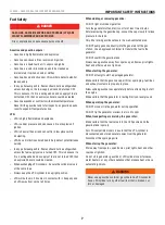
 

WARNING

Always remember to plug your appliances directly into the 
generator and do not plug the generator power cord into any 
electrical outlet or connect to the circuit breaker panel in your 
home. Connecting a generator to your home’s electric utility 
company’s power lines, or to another power source, called 
‘backfeeding’ is a dangerous practice that is illegal in many 
states and municipalities. 

This action if done incorrectly could damage your generator, 
appliances and could cause serious injury or death to you 
or a utility worker when attempting to restore power during 
an outage occurrence in the neighborhood who may then 
unexpectedly encounter high voltage on the utility line and 
suffer a fatal shock. 

Whether injuries occur or not, if installed incorrectly and not to 
applicable laws and codes, you may be subject to fines or the 
utility company may disconnect your home power should this 
practice be found in your home.

If the generator will be connected to a building electrical 
system, those connections must isolate the generator power 
from the utility power. You are responsible for ensuring your 
generator’s electricity does not backfeed into the electric 
utility power lines. These connections must comply with all 
applicable laws and codes – Consult your local utility company 
or a qualified electrician to properly install this connection. 

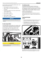
Do Not Overload Generator

Capacity

Follow these simple steps to calculate the running and starting 
watts necessary for your purposes: 

1.  Select the electrical devices you plan on running at the same 

time.

2.  Total the running watts of these items. This is the amount of 

power you need to keep your items running.

3.  Identify the highest starting wattage of all devices identified 

in step 1. Add this number to the number calculated in step 2. 
Starting wattage is the surge of power needed to start some 
electric driven equipment. Following the steps listed under 
“Power Management” will guarantee that only one device will 
be starting at a time.
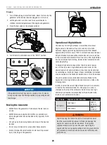
Power Management

Use the following formula to convert voltage and amperage to 
watts:

Volts × Amps = Watts

Содержание 100899

Страница 1: ... understood before operating the product Failure to do so could result in serious injury This manual should remain with the product Specifications descriptions and illustrations in this manual are as accurate as known at the time of publication but are subject to change without notice Covered by one or more of the following U S Patent Numbers 10 598 101 10 221 780 and other U S and foreign patents...

Страница 2: ...t all carbon monoxide risks you ll be better prepared to protect your family from this colorless oderless threat CARBON MONOXIDE SAFETY THE BIG PICTURE KNOW THE SYMPTOMS Headache Nausea Shortness of breath Dizziness Fatigue STAY ALERT WITH CARBON MONOXIDE DETECTORS POINT FUMES AWAY FROM NEARBY PEOPLE KEEP IT OUTSIDE AND AWAY FROM DOORS WINDOWS AND GARAGES ALWAYS READ THE OPERATOR S MANUAL FIRST MA...

Страница 3: ...e Generator 23 Operation at High Altitude 23 Maintenance 24 Cleaning the Generator 24 Changing the Engine Oil 24 Cleaning and Adjusting the Spark Plug 25 Cleaning the Air Filter 25 Cleaning the Spark Arrestor 25 Adjusting the Governor 26 Maintenance Schedule 26 Storage 26 Short Term Storage up to 30 days 26 Mid Term Storage 30 days 1 year 27 Long Term Storage more than 1 year 27 Removing from Stor...

Страница 4: ...ry effort has been made to ensure the accuracy and completeness of the information in this manual at the time of publication and we reserve the right to change alter and or improve the product and this document at any time without prior notice CPE highly values how our products are designed manufactured operated and serviced as well as providing safety to the operator and those around the generato...

Страница 5: ...tating parts can entangle hands feet hair clothing and or accessories Traumatic amputation or severe laceration can result Keep hands and feet away from rotating parts Tie up long hair and remove jewelry DO NOT wear loose fitting clothing dangling drawstrings or items that could become caught DANGER Generator produces powerful voltage DO NOT touch bare wires or receptacles DO NOT use electrical co...

Страница 6: ...r laceration When starting engine pull the recoil cord slowly until resistance is felt and then pull rapidly to avoid kickback DO NOT start or stop the engine with electrical devices plugged in and turned on CAUTION Exceeding the generator s running capacity can damage the generator and or electrical devices connected to it DO NOT overload the generator DO NOT tamper with the governed speed DO NOT...

Страница 7: ... will burn skin if it comes in contact with it Keep any and all LPG away from skin at all times When adding or removing gasoline DO NOT light or smoke cigarettes Turn the generator off and let it cool for at least two minutes before removing the gasoline cap Loosen the cap slowly to relieve pressure in the tank Only fill or drain gasoline outdoors in a well ventilated area DO NOT pump gasoline dir...

Страница 8: ...Artwork Notes 3mm corner radius 2mm safe margin Revision Changes B Changed Octane rating from 85 to 87 20200421 This artwork belongs to Champion Power Equipment The contents are confidential and privileged and shall not be disclosed to or used by or for outside parties without the explicit consent of Champion Power Equipment Fuel C CHAMPION POWER EQUIPMENT INC 12039 SMITH AVENUE SANTA FE SPRINGS C...

Страница 9: ...ts before operation Electric Shock Failure to use in dry conditions and to observe safe practices can result in electric shock Improper connections to a building can allow current to backfeed into utility lines creating an electrocution hazard A transfer switch must be used when connecting to a building Fire Explosion Fuel and its vapors are extremely flammable and explosive Fire or explosion can ...

Страница 10: ...on of these symbols will allow you to more safely operate the product SYMBOL MEANING Propane Hose Inlet Engine Run Propane Engine Run Gasoline Choke Stop or Off ECO Economy Mode Button Low Oil SYMBOL MEANING Overload Reset Button Circuit Breaker Reset Push Ground Terminal Neutral Floating Neutral circuit IS NOT electrically connected to the frame ground of the generator Parallel Connection s USB C...

Страница 11: ...osition 5 Pull the recoil cord 6 Turn fuel selector dial to gasoline icon for gasoline RUN 7 Plug in desired device Stopping the Engine 1 Turn off and unplug all connected electrical loads 2 Turn the fuel vent lever to the OFF position 3 Turn the dial to the STOP position For adding fuel and starting the engine with LPG see Add Fuel Propane LPG in Assembly section and Starting the Engine Propane L...

Страница 12: ...of the controls and features Save this manual for future reference Generator 1 Carrying Handle Used to lift or carry the unit 2 Recoil Starter Used to manually start the engine 3 Control Panel See Control Panel section 4 Fuel Cap Remove to add fuel 5 Fuel Lever Vent Turn this valve to the ON position to supply air to the tank 6 Spark Plug Access Cover 7 Maintenance Cover 8 Muffler ECO 1 2 3 7 8 6 ...

Страница 13: ...wo inverters together for increased power output parallel kit sold separately 6 LPG Inlet Used to connect LPG fuel source to generator 7 Ground Terminal Consult an electrician for local grounding regulations 8 Fuel Selector Dial Used to turn on gasoline or propane LPG fuel source operate the choke plate and stop the engine RECEPTACLES A A 2 120V AC 20A NEMA 5 20R May be used to supply electrical p...

Страница 14: ...a residential installation This equipment generates uses and can radiate radio frequency energy and if not installed and used in accordance with the instructions may cause harmful interference to radio communications However there is no guarantee that interference will not occur in a particular installation If this equipment does cause harmful interference to radio or television reception which ca...

Страница 15: ...s will void your warranty NOTICE The generator rotor has a sealed pre lubricated ball bearing that requires no additional lubrication for the life of the bearing NOTICE The recommended oil type for typical use is 10W 30 automotive oil If running generator in extreme temperatures refer to the following chart for recommended oil type 20 0 20 40 60 Ambient temperature Recommended Engine Oil Type 80 1...

Страница 16: ...on if overfilled and can affect the stable running condition of the generator 3 Screw on the gasoline cap and wipe away any spilled fuel CAUTION Use unleaded gasoline with a minimum octane rating of 87 and an ethanol content of 10 or less by volume DO NOT light cigarettes or smoke when filling the tank DO NOT mix oil and gasoline DO NOT overfill the tank Fill tank to approximately in 6 4 mm below ...

Страница 17: ...or kinks in the LPG hose CAUTION Do not allow children to tamper or play with the LPG cylinder or hose connections CAUTION Use approved LPG cylinders equipped with an OPD overfilling prevention device valve Always keep the cylinder in a vertical position with the valve on top and installed at ground level on a flat surface Cylinders must not be installed near any heat source and should not be expo...

Страница 18: ...r system DO NOT operate or store the generator in wet weather conditions such as rain or snow Using a generator in wet conditions could result in serious injury or death due to electrocution In some state s generators may be required to be registered with the local utility company when used at construction sites and may be subject to additional rules and regulations consult your local municipal au...

Страница 19: ...9 CSA listed plug in surge suppressors on the outlets feeding your sensitive equipment Surge suppressors come in single or multi outlet styles They re designed to protect against virtually all short duration voltage fluctuations Starting the Engine Gasoline 1 Make certain the generator is on a flat level surface 2 Disconnect all electrical loads from the generator Never start or stop the generator...

Страница 20: ...to run make certain that the generator is on a flat level surface The engine is equipped with a low oil sensor that will prevent the engine from running when the oil level falls below a critical threshold Starting the Engine Propane LPG 1 Make certain the generator is on a flat level surface 2 Disconnect all electrical loads from the generator Never start or stop the generator with electrical devi...

Страница 21: ... NOT overload the generator WARNING Always remember to plug your appliances directly into the generator and do not plug the generator power cord into any electrical outlet or connect to the circuit breaker panel in your home Connecting a generator to your home s electric utility company s power lines or to another power source called backfeeding is a dangerous practice that is illegal in many stat...

Страница 22: ...runs at normal speed continuously CAUTION For periods of high electrical load or momentary fluctuations the Eco Mode should be off Parallel Operation The Champion model 100899 is parallel ready and can be operated in parallel with another Champion unit to increase the total available electrical power A Champion model 100319 parallel kit sold separately is required for parallel operation For a list...

Страница 23: ...At high altitudes increased exhaust emissions can also result due to the increased enrichment of the air fuel ratio Other high altitude issues can include hard starting increased fuel consumption and spark plug fouling To alleviate high altitude issues other than the natural power loss CPE can provide a high altitude carburetor main jet The alternative main jet and installation instructions can be...

Страница 24: ... can also contaminate the fuel system 1 Use a damp cloth to clean exterior surfaces of the generator 2 Use a soft bristle brush to remove dirt and oil 3 Use an air compressor 25 PSI to clear dirt and debris from the generator 4 Inspect all air vents and cooling slots to ensure that they are clean and unobstructed To prevent accidental starting remove and ground the spark plug wire before performin...

Страница 25: ...ess cap and maintenance cover Cleaning the Air Filter 1 Remove the maintenance cover 2 Locate the air filter plastic cover and remove by pinching the clips together and pulling the cover off 3 Remove the foam element 4 Wash in liquid detergent and water Squeeze thoroughly dry in a clean cloth 5 Saturate in clean engine oil 6 Squeeze in a clean absorbent cloth to remove all excess oil 7 Place the f...

Страница 26: ...URS OR PRIOR TO EACH USE Check oil level Clean around air intake and muffler Check propane LPG hose for leaks FIRST 5 HOURS BREAK IN Change oil EVERY 50 HOURS OR ANNUALLY Clean air filter Change oil if operating under heavy load or in hot environments EVERY 100 HOURS OR ANNUALLY Change oil Clean adjust spark plug Clean spark arrestor Clean fuel valve filter EVERY 250 HOURS Clean combustion chamber...

Страница 27: ... from generator 2 Place inverter on blocks to allow appropriate gasoline container or pan to slide under inverter 3 Remove the maintenance cover 4 Turn the dial to the gasoline RUN position 5 Using a Phillips screwdriver rotate drain screw counterclockwise 3 full turns Gasoline will drain through clear tubing out underneath the inverter Make sure draining gasoline empties into an appropriate conta...

Страница 28: ...ng carbon monoxide will cause nausea dizziness fainting or death If you start to feel dizzy or weak get to fresh air immediately To avoid accidental or unintended ignition of your generator during periods of storage the following precautions should be followed When storing the generator make sure the fuel dial is set to the STOP position ...

Страница 29: ... Type 80 100 120 28 9 F C 17 8 6 7 4 4 15 6 26 7 37 8 48 9 10W 30 5W 30 Full Synthetic 10W 40 5W 30 NOTICE Temperature will affect engine oil and engine performance Change the type of engine oil used based on temperature shown in the Recommended Engine Oil Type table Fuel Specifications Use unleaded gasoline with a minimum octane rating of 87 and an ethanol content of 10 or less by volume DO NOT U...

Страница 30: ...100899 2500W Dual Fuel Inverter Generator Specifications 30 Parts Diagram ...

Страница 31: ...249 0003 Bolt M5 x 12 1 33 1ZC7DFA07 Engine 79cc 1 34 100033099 0006 Big Flange Bolt M6 x 18 2 35 100131884 Tube Sheath Silicon Resin 1 36 100131883 Fuel Tube L 275mm 1 Part Number Description Qty 37 100090871 Clamp 2 Ø9 7 x 8 1 38 100009020 Fuel Strainer 1 39 100072874 Rear Air Guide 1 40 100011004 0001 Self tapping Screw ST4 2 x 25 4 41 100092440 0007 Housing Assembly Left Handle Black 1 42 1001...

Страница 32: ...Self locking Quick Connector 1 86 100011450 0001 Nut M4 4 87 100157217 Sliding Block Mounting Seat 1 88 100157221 Spring Mounting Seat 1 89 100157215 Mounting Plate 1 90 100160807 Nut M10 1 91 100160808 Gas Hose 1 92 100715460 Fuel Solenoid Valve Controller 1 93 100715007 Mounting Cover Gas Pressure Valve 1 94 100032967 0004 Self tapping Screw ST4 2 x 16 1 95 100714544 Mounting Plate Recoil Cord 1...

Страница 33: ... 33 Engine Parts Diagram 4 55 8 51 54 66 64 63 44 31 56 43 42 37 45 2 25 26 23 3 12 35 36 11 9 10 34 13 14 22 16 17 18 19 47 71 52 53 24 48 27 58 33 32 21 57 49 50 20 15 59 62 7 5 38 65 1 70 6 30 29 72 20 21 41 40 39 60 61 33 46 50 50 68 69 67 74 75 76 73 28 ...

Страница 34: ... 4 34 100075061 Push Rod 2 35 100075059 Valve Exhaust 1 36 100159354 Valve Intake 1 37 100075036 Lifter Valve 2 Part Number Description Qty 38 100075040 Piston Ring Set 1 39 100088147 1st Piston Ring 1 40 100088148 2nd Piston Ring 1 41 100088146 Oil Ring 1 42 100075038 Circlip 2 43 100075039 Wrist Pin 1 44 100159355 Piston 1 45 100075037 Connecting Rod 1 46 100091043 Bolt Connecting Rod 2 47 10008...

Страница 35: ...ator Specifications 35 Part Number Description Qty 74 100131960 Fuel Bowl O Ring 1 75 100715806 Main Jet Standard 1 100715807 Main Jet Altitude 1000 2000m 100715794 Main Jet Altitude 2000 3000m 76 100715796 Fuel Bowl Mounting Bolt Gasket 1 ...

Страница 36: ...100899 2500W Dual Fuel Inverter Generator Specifications 36 Wiring Diagram ...

Страница 37: ...e Connecting Electrical Loads Dirty air filter Clean or replace air filter Choke in wrong position Move choke until it stops under RUN position or push in completely Engine is running but no AC output Poor cord connection Check all connections Circuit breaker is open Reset circuit breaker Loose wiring Inspect and tighten wiring connections AC Overload Button illuminated red Reduce AC load and pres...

Страница 38: ...perly or connected incorrectly to any electrical component Normal maintenance is not covered by this warranty and is not required to be performed at a facility or by a person authorized by CPE Other Exclusions This warranty excludes Cosmetic defects such as paint decals etc Wear items such as filter elements o rings etc Accessory parts such as starting batteries and storage covers Failures due to ...

Страница 39: ...n system catalytic converter and other exhaust emission related assemblies Where a warrantable condition exits CPE will repair your small off road engine SORE at no cost to you including diagnosis parts and labor MANUFACTURER S WARRANTY COVERAGE This exhaust and evaporative emission control system is warranted for two years If any exhaust and evaporative emission related part on your engine or equ...

Страница 40: ...ted for the period of time prior to the first scheduled replacement point for that part If the part fails prior to the first scheduled replacement the part shall be repaired or replaced by CPE according to Subsection d below Any such exhaust and evaporative emissions related part repaired or replaced under the ECS Warranty shall be warranted for the remainder of the ECS Warranty Period prior to th...

Страница 41: ...ive Controls Fuel Tank Fuel Cap Fuel Lines for liquid fuel and fuel vapors Fuel Line Fittings Clamps Pressure Relief Valves Control Valves Control Solenoids Electronic Controls Vacuum Control Diaphragms Control Cables Control Linkages Purge Valves Gaskets Liquid Vapor Separator Carbon Canister Canister Mounting Brackets Carburetor Purge Port Connector TO OBTAIN WARRANTY SERVICE You must take your ...

Отзывы: