background image

6

Straight Door
Arm Section

C

u

r

v

ed Door

Arm Section

Header  Bracket

UP

CE

ILI

N

MO

U

N

T O

N

LY

Sprocket
Co

u

pling

Remote Control
Visor Clip


Trolley

Rail S

u

pport

Braces (4)

Rail Assem

b

ly

Hanging Brackets

Door Bracket

M

u

lti-F

u

nction

Door Control Panel

LOCK

LIGHT

Safety La

b

els

and

Literat

u

re

The Protector System

®

(2) Safety Re

v

ersing Sensors

(1 Sending Eye and 1 Recei

v

ing Eye)

w

ith attached 2-Cond

u

ctor 

W

hite & 

W

hite/Black Bell 

W

ire

Safety Re

v

ersing Sensor

Mo

u

nting Bracket (2)

2-Cond

u

ctor Bell 

W

ire

W

hite & 

W

hite/Red

Motor Unit 

w

ith 2 Light Lenses

Header/Rail
 Brackets

SECURITY

®

Keyless Entry

SECURITY

®

3-B

u

tton Remote Control

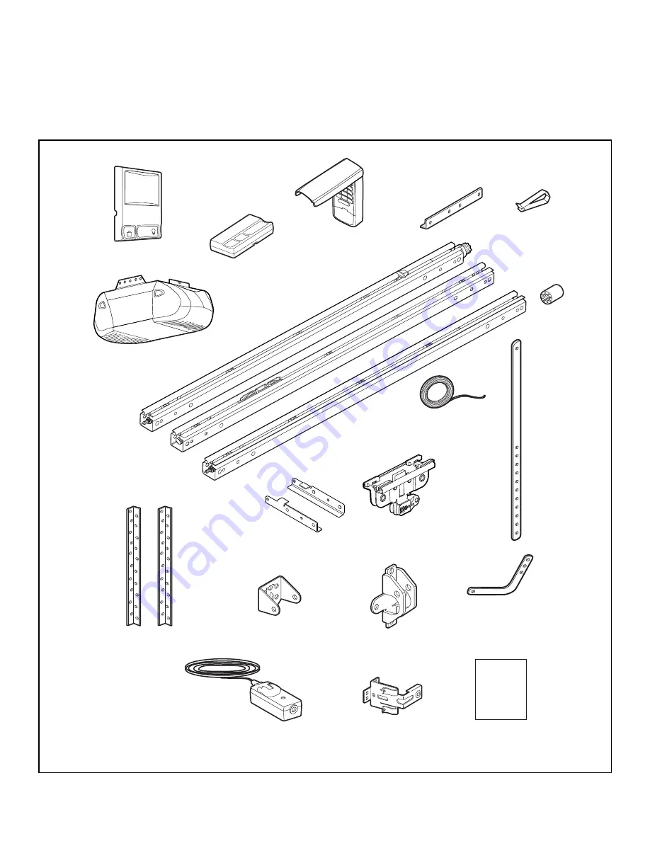
Your garage door opener is packaged in one carton which
contains the motor unit and all parts illustrated below.
Accessories will depend on the model purchased. If
anything is missing, carefully check the packing material.

PARTS MAY BE STUCK IN THE FOAM. Hardware for
assembly and installation is shown on the next page.
Save the carton and packing material until installation and
adjustment is complete.

Carton Inventory

Содержание 995XD

Страница 1: ...r s Manual Please read this manual and the enclosed safety materials carefully Fasten the manual near the garage door after installation The door WILL NOT CLOSE unless the Protector System is connecte...

Страница 2: ...re of your garage door opener 32 Having a problem 33 Diagnostic chart 34 Programming 35 36 To add or reprogram a hand held remote control 35 To erase all codes 35 3 Button remotes 35 To add reprogram...

Страница 3: ...or their hardware all of which are under EXTREME tension Disable ALL locks and remove ALL ropes connected to garage door BEFORE installing and operating garage door opener to avoid entanglement Prepa...

Страница 4: ...ng upon garage construction extension brackets or wood blocks may be needed to install sensors Installation Step 4 Alternate floor mounting of the safety reversing sensor will require hardware not pro...

Страница 5: ...FINISHED CEILING Support bracket fastening hardware is required See page 19 Safety Reversing Sensor Access Door Gap between floor and bottom of door must not exceed 1 4 6 mm Wall mounted Door Control...

Страница 6: ...l Wire Safety Reversing Sensor Mounting Bracket 2 2 Conductor Bell Wire White White Red Motor Unit with 2 Light Lenses Header Rail Brackets SECURITY Keyless Entry SECURITY 3 Button Remote Control Your...

Страница 7: ...Screw 5 16 9x1 5 8 2 Hex Bolt 5 16 18x7 8 4 Clevis Pin 5 16 x1 1 4 1 Lag Screw 5 16 18x1 7 8 2 Screw 6ABx1 1 4 2 Screw 6 32x1 2 Spacer Self Threading Screw 1 4 14x5 8 INSTALLATION HARDWARE Hardware I...

Страница 8: ...The back rail has a black gear on one end The header rail has a black plastic rack inside the rail on the screw The remaining section is the center rail NOTE Use caution when handling the center rail...

Страница 9: ...connection Figure 3 6 Place the c clip onto the long journal shaft center rail to ensure that the sleeve does not slide Figure 4 7 Slide the center rail so that the center rail and rail brace holes ar...

Страница 10: ...as shown 2 Slip the coupling over the rail sprocket 3 Slide the rail through the motor unit bracket until the coupling fits securely over the motor unit sprocket 4 Align the four bolt holes in the rai...

Страница 11: ...watches rings or loose clothing while installing or servicing opener They could be caught in garage door or opener mechanisms 9 Install wall mounted garage door control within sight of the garage doo...

Страница 12: ...the door NOTE If the total number of inches exceeds the height available in your garage use the maximum height possible or refer to page 13 for ceiling installation To prevent possible SERIOUS INJURY...

Страница 13: ...on the vertical mark no more than 6 15 cm from the wall Make sure the arrow is pointing toward the wall The bracket can be mounted flush against the ceiling when clearance is minimal Mark the side ho...

Страница 14: ...he rail to clear the spring Position the header rail bracket against the header bracket Align the bracket holes and join with a clevis pin 5 16 x2 3 4 as shown Spacer can be installed on either side o...

Страница 15: ...ove the floor Either can be installed on the left or right of the door as long as the sun never shines directly into the receiving eye lens The mounting brackets are designed to clip onto the track of...

Страница 16: ...p hugging the back edge of the track as shown in Figure 1 If your door track will not support the bracket securely wall installation is recommended Wall installation Figure 2 3 Place the bracket again...

Страница 17: ...at the door header see Figure 6 2 Run the wires through wire clip at the top of the rails NOTE If your access door is near the garage door you may choose to install the door control at this time and...

Страница 18: ...nt for setting an ideal door to rail distance Remove foam packaging Raise the opener onto a stepladder You will need help at this point if the ladder is not tall enough Open the door all the way and p...

Страница 19: ...nit as in Figures 1 and 2 or to the mounting tabs as shown in Figure 3 Then continue with step 6 below 1 Measure the distance from each side of the motor unit to the structural support 2 Cut both piec...

Страница 20: ...e the terminal block on the back panel Figure 4 5 Strip 7 16 11 mm of insulation from each set of bell wires Connect bell wires to the quick connect terminals as follows white to white and white red t...

Страница 21: ...outer trolley Adjust rope length so the handle is 6 feet 1 83 m above the floor Ensure that the rope and handle clear the tops of all vehicles to avoid entanglement Secure with an overhand knot NOTE I...

Страница 22: ...ructed alignment is required Loosen the sending eye wing nut and readjust aiming directly at the receiving eye Lock in place Loosen the receiving eye wing nut and adjust the sensor until it receives t...

Страница 23: ...Secure the door bracket using the two 1 4 14x5 8 self threading screws Figure 2A Alternately use two 5 16 bolts lock washers and nuts not provided Figure 2B Metal insulated or light weight factory rei...

Страница 24: ...INUM STEEL DOORS WITH GLASS PANEL ETC NOT PROVIDED ONE PIECE DOORS Please read and comply with the warnings and reinforcement instructions on the previous page They apply to one piece doors also Cente...

Страница 25: ...re 3 Hole alignment alternative If holes in curved arm are above holes in straight arm disconnect straight arm Cut about 6 15 cm from the solid end Reconnect to trolley with cut end down as shown Brin...

Страница 26: ...g Fastener Straight Arm Bolts 5 16 18x7 8 Door Bracket Clevis Pin 5 16 x1 1 4 Curved Door Arm Press the Door Control push button The trolley will travel to the fully closed position Manually close the...

Страница 27: ...r does not close completely Increase down travel Turn the down limit adjustment screw counterclockwise One turn equals 2 5 cm of travel If door still won t close completely try lengthening the door ar...

Страница 28: ...ockwise Make small adjustments until the door completes a close cycle After each adjustment run the opener through a complete travel cycle Do not increase the force beyond the minimum amount required...

Страница 29: ...un the opener through 3 or 4 complete travel cycles to test adjustment If the unit continues to fail the Safety Reverse Test call for a trained door systems technician IMPORTANT SAFETY CHECK Test the...

Страница 30: ...19 Bulb power is 100 watts maximum Security light feature Lights will also turn on when someone walks through the open garage door With a Multi Function Door Control Panel this feature may be turned o...

Страница 31: ...ht feature Press the Light button to turn the opener light on or off It will not control the opener lights when the door is in motion If you turn it on and then activate the opener the light will rema...

Страница 32: ...he lithium battery should produce power for up to 5 years NOTICE To comply with FCC and or Industry Canada rules IC adjustment or modifications of this receiver and or transmitter are prohibited excep...

Страница 33: ...er adjustments to force or travel limits The need for occasional adjustment for the force and limit settings is normal Weather conditions in particular can affect door travel Manually check door for b...

Страница 34: ...door control touch wires together If motor unit activates replace door control If motor unit does not activate disconnect door control wires from motor unit Momentarily short across red and white ter...

Страница 35: ...ONTROL PROGRAMMING Your garage door opener has already been programmed at the factory to operate with your hand held remote control The door will open and close when you press the large push button Be...

Страница 36: ...ce when the PIN has been learned Test by pressing the new PIN then press Enter The door should move To set a temporary PIN You may authorize access by visitors or service people with a temporary 4 dig...

Страница 37: ...O NO DESCRIPTION 1 41A5273 9 Multi function door control 2 953D 3 Button remote control 3 10A20 3V 2032 Lithium battery 4 29B137 Visor clip 5 41A2828 Emergency release rope handle assy 6 41B4494 1 2 C...

Страница 38: ...drive assy complete 6a 20B21 1 Drive belt 7 41C4672 Screw drive RPM kit KEY PART NO NO DESCRIPTION 8 41A4837 1 Worm gear and retainer 9 41A6335 Low voltage wire harness 9a 41A6334 High voltage wire h...

Страница 39: ...nutes when it detects a person entering the garage Sensor can be easily deactivated when desired 940D Extension Brackets Optional For safety sensor installation onto the wall or floor To order call 1...

Страница 40: ...re confirmed to be defective and covered by this limited warranty will be repaired or replaced at Seller s sole option at no cost to you and returned pre paid Defective parts will be repaired or repla...

Отзывы: