


Chapter 2
5
When the Soft-OFF by PWR-BTTN function is enabled, pushing the power button
rapidly will switch the system to Suspend mode. Any occurrence of external activities
such as pressing a key on the keyboard or moving the mouse will bring the system back
to Full-On. Pushing the button while in Full-On mode for more than [
4 seconds
] will
switch the system completely off. See Over-ride Power Button Operation diagram.
2.
P-LED
(Power LED Connector)
The power indicator LED shows the system's power status. It is important to pay
attention to the correct cables and pin orientation (i.e., not to reverse the order of these
two connectors.)
3.
G-BTN/G-LED
(Green Button Switch/LED Connector)
Some ATX cases provide a Green button switch, which is used to put the system in
Suspend mode. In Suspend mode, the power supply to the system is reduced to a trickle,
the CPU clock is stopped, and the CPU core is in its minimum power state. The system
is woken up whenever the keyboard or mouse is touched. The system resumes in
different ways as defined by Power Management Setup screen in BIOS.
4.
RESET
(System Reset Switch Connector)
This connector should be connected to the reset switch on the front panel of the system
case. The reset switch allows you to restart the system without turning the power off.
5.
SPEAKER
(Speaker Connector)
This 4-pin connector connects to the case-mounted speaker.
6.
HD-LED
(IDE Activity LED Connector)
The IDE activity LED lights up whenever the system reads/writes to the IDE devices.
FD1 (Floppy Connector)
The motherboard provides a standard floppy disk drive connector that supports 360K,
720K, 1.2M, 1.44M and 2.88M floppy disk types, use this connector to connect 34 pins
of Floppy.
IDE1 / 2 (IDE Hard-Disk Connector)
The motherboard has a 32-bit Enhanced PCI IDE and Ultra ATA66/100/133 controller
that provides PIO mode 0~4, Bus Master, and Ultra ATA66/100/133 function. This
connector is used for connecting 40 pins of ATAPI devices.
IDE 1 only connects two IDE devices. (
Primary
Master/Slave)
IDE 2 only connects two IDE devices. (
Secondary
Master/Slave)
JP1 (CMOS Clear Jumper)
There is a CMOS RAM on board that has a power
supply from external battery to keep the data and
system configuration. To clear the contents of the
CMOS, please follow the steps below.
1. Disconnect the system power supply from the power
source.
2. Set the jumper cap at location [
2-3
] for <
5 seconds
>, and then set it back to the default
position.
3. Connect the system's power and then start the system.
4. Enter BIOS's CMOS Setup Utility and choose Load Setup Defaults. Type [
Y
] and then
press [
Enter
] to continue.
5. Set the system configuration in the Standard CMOS Setup menu.
JP6 (Enable/Disable USB 0/1 Device Wake-Up Jumper)
A USB keyboard hot key or a USB mouse click can
wake up this board. To use this function, select a hot key
of your choice at the USB Resume from S3 option under
Wake Up Events in the BIOS's Power On Management
Pin
Definition
1-2 Normal (default)
2-3 Clear CMOS Data
Pin
Definition
1-2
Disable (default)
2-3
Enable
Chapter 2
6
screen. You must also set this jumper's cap to pins
2-3
to use this function.
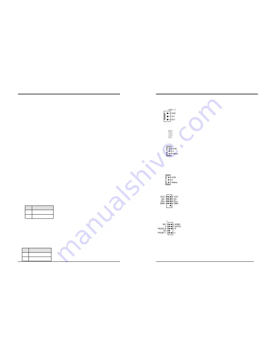
FAN1 / FAN2 (CPU/System Cooling Fan Connectors)
The board's management extension hardware is able to detect
the CPU and system fan speed in rpm (revolutions per minute).
The wiring and plug may vary depending on the manufacturer.
On standard fans, the red is positive (+12V), the black is ground,
and the yellow wire is the rotation signal.
CN2/CN2A (CD-ROM Audio-in Connector)
Use the audio cable enclosed with your CD-ROM disk drive to
connect the CD-ROM to your motherboard. This will enable
your CD-ROM's audio function.
CN5 [WOL (Wake-on-LAN) Connector]
Enable the Wake Up On LAN selection in BIOS's Power
Management Menu to use this function. The capability to
remotely manage PCs on a network is a significant factor in
reducing administrative and ownership costs. Magic Packet
technology is designed to give WOL capability to LAN controller. This header is used to
connect an add-in NIC (Network Interface Card) which gives WOL capability to the
motherboard.
CN5A [WOM (Wake-on-Modem) Connector]
Enable the Wake Up On Modem selection in BIOS's Power
Management Menu to use this function. This header is used to
connect an add-in modem card, which gives WOM capability to
the motherboard.
CN23/CN23A (Front USB Connector for USB 2/3 and 4/5)
USB Port 2/3
Æ
CN23,
USB Port 4/5
Æ
CN23A
If you want to use a USB Keyboard, you must enable the USB
keyboard support function in BIOS's Integrated Peripherals
menu (See Section 3.4). This board contains a USB Host
controller and includes a root hub with two connectors for
optional USB Adaptor (USB 2/3 and 4/5).
CN24 (Front Audio Connector)
This connector give you the option of a front panel audio jack
cable ext. to be plug into a special custom designed system case.
Simply remove the two jumper caps at pin [
5-6
] and [
9-10
] then
plug it into the (optional) cable ext. connector. Pin [
5-6
] and
[
9-10
] are shorted (default) to enable the back panel audio
function.


