background image

Landing Procedures. 

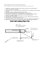
VFR Landing briefing procedure. 

Announce verbally

1. Type of Approach & Landing Runway

2. Aiming & Touchdown Point

3. Wind Direction & Speed Pattern Altitude 

4. Go-Around Criteria & Plan

Example

:

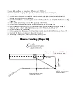
 “This will be a normal flaps full landing on runway 13 with an intended 

touchdown point of the one thousand foot markers, aiming point will be 3 stripes prior, we 
can expect a left crosswind of 5 knots”.


Stabilized Approach 

Definition:  A stabilized approach is one in which the pilot establishes and maintains a 
constant angle glide-path towards a predetermined point on the landing runway. It is based 
on the pilot’s judgment of certain visual cues, and depends on a constant final descent 
airspeed and configuration (FAA-H-8083- 3A, p.8-7). 

Approach Gust factors.  

Slightly higher approach speeds should be used under turbulent or gusty wind conditions. 
Add 1⁄2 the gust factor to the normal approach speed. For example, if the wind is reported 8 
gusting to 18 knots, the gust factor is 10 knots. Add 1⁄2 the gust factor, 5 knots in this 
example, to the normal approach speed.  

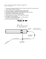
Before landing checklist. 

This is a memory item that needs to get memorized prior to the second flight

Announce verbally

1. Seat belts - fastened

2. Fuel selector - both

3. Mixture set

4. Fuel pump on

5. Gen/Bat master - ON

6. Mags - BOTH

7. Lights - as required

8. Flaps - as required

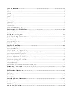
Содержание C172S Nav III

Страница 1: ...C172S Nav III Training Manual Crosswinds Aviation 1st Edition...

Страница 2: ...g procedure Flaps 20 FULL 17 Maneuver standards 10 5 1 3x Vso approach touchdown within 400 of selected point 17 Short field Landing procedure Flaps FULL 18 Maneuver standards 10 5 1 3x Vso approach t...

Страница 3: ...n oil containers and risk contamination The engine has a full pressure wet sump type lubrication system Oil is drawn from the sump through an oil suction strainer screen into the engine driven oil pum...

Страница 4: ...left of the flap switch indicates flap travel in degrees The wing flap system circuit is protected by a 10 ampere circuit breaker labeled FLAP on the left side of the control panel Pitot static system...

Страница 5: ...eservoir tank fuel flows through the auxiliary fuel pump past the fuel shutoff valve through the fuel strainer to an engine driven fuel pump From the engine driven fuel pump fuel is delivered to the f...

Страница 6: ...ling on the left firewall The alternator and battery are controlled through the MASTER switch ALT and BAT found near the top of the pilot s switch panel Power is supplied to most electrical circuits t...

Страница 7: ...in amber indicates that the battery is discharging In the event the alternator is not functioning or the electrical load exceeds the output of the alternator the main battery ammeter indicates the ma...

Страница 8: ...reference lines and the magenta line that appears above the heading indicator to identify a standard rate or half standard rate turn Outside air temperature OAT displays on PFD under the airspeed tape...

Страница 9: ......

Страница 10: ...Empty Weight Maximum Ramp Weight 2558lbs Maximum Take off weight weight 2550lbs Speed KTS Description Airspeed indicator markings Vso 40 Stall speed in landing configuration Vs 48 Stall speed with ze...

Страница 11: ...all in the center HSI DG aligned with the compass Compass no cracks no leaks no bubbles deviation card present Flight instrument check during taxi Turn coordinator indicating a turn Inclinometer Ball...

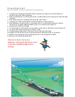
Страница 12: ...Mixture to cutoff Fuel selector magnetos and battery master off Touchdown at lowest speed possible...

Страница 13: ...t rudder as required for turning tendencies 5 Airspeed Alive 6 Start smooth rotation at 55 KIAS 7 Accelerate to 74 KIAS VY 8 After Takeoff Checklist 1 000 AGL 1 Line up on centerline 2 Smoothly apply...

Страница 14: ...rotate at 51 KIAS or as calculated with performance charts 9 Accelerate to 56 KIAS Vx or as calculated with performance charts 10 Clear of obstacles flaps cruise 11 Accelerate to 74 KIAS VY 12 After T...

Страница 15: ...west possible airspeed remain in ground effect 6 In ground effect accelerate to 62 KIAS begin climb 7 Clear of obstacles flaps Cruise 8 Accelerate to 74 KIAS VY 9 After Takeoff Checklist out of 1 000...

Страница 16: ...t on the landing runway It is based on the pilot s judgment of certain visual cues and depends on a constant final descent airspeed and configuration FAA H 8083 3A p 8 7 Approach Gust factors Slightly...

Страница 17: ...touchdown point on extended base or on extended final when ready to descend out of pattern altitude Reduce power to 1700 and select flaps 10 6 Descend out of TPA at 90 KIAS 7 Turn base approx 45 degr...

Страница 18: ...t of pattern altitude Reduce power to 1700 and select flaps 10 6 Descend out of TPA at 90 KIAS 7 Turn base approx 45 degrees from touchdown point slow to 80 KIAS and select flaps 20 8 Select flaps FUL...

Страница 19: ...ttern altitude Reduce power to 1700 and select flaps 10 6 Descend out of TPA at 90 KIAS 7 Turn base approx 45 degrees from touchdown point slow to 80 KIAS and select flaps 20 8 Select flaps FULL and m...

Страница 20: ...n the downwind 5 When abeam touchdown point power to idle 6 Adjust pitch to maintain appropriate glide speed 7 Plan and maneuver to execute a safe approach and landing 8 Use flaps 0 FULL as necessary...

Страница 21: ...tended base or on extended final when ready to descend out of pattern altitude Reduce power to 1700 and select flaps 10 6 Descend out of TPA at 90 KIAS 7 Turn base approx 45 degrees from touchdown poi...

Страница 22: ...lout 5 From straight and level coordinate aileron and rudder to roll into a 45 o bank 6 Add a small amount of power 100 200 RPM as you roll through 30 o of bank 7 Maintain altitude and airspeed 8 Refe...

Страница 23: ...rspeed that is 5 to 10 knots above published Vso 12 Maintain directional control using outside visual references and inside instrument references 13 Practice gentle climbs descents and turns at consta...

Страница 24: ...ts NOTE Minimum safe altitude for this maneuver is 1500 AGL Crosswinds Aviation requires a minimum altitude of 3 500 AGL Power Off stalls are performed in the landing Configuration 1 Perform clearing...

Страница 25: ...neuver 45 to the downwind with the first circuit to the left Downwind 1 Roll wings level parallel to the boundary 2 Maintain distance about 1 2 mile from boundary 3 At field boundary edge turn first c...

Страница 26: ...st turn to the left at the highest groundspeed and steepest bank angle max 45 degrees 11 Bank angle will gradually need to be decreased to the upwind point slowest groundspeed 12 From the upwind point...

Страница 27: ...est bank angle not to exceed 30 degrees 8 Directly crosswind moderate bank angle and decrease as the airplane turns upwind 9 Maintain coordinated flight throughout 10 Cross the line feature with wings...

Страница 28: ......

Страница 29: ...ts The C172S has an aluminum propeller A True B False How many AMP breaker protects the flap motor A 10 B 15 C 20 How many volts is the C172S electrical system A 12 B 14 C 28 What would an illuminated...

Страница 30: ...7kts C 20kts The C172S requires the AHRS to be operative for VFR flight A True B False Brake fluid is what color A Red B Clear C Yellow List all the V speeds for the C172S For every 1 000 of altitude...

Страница 31: ...B False...

Отзывы: