background image

CESSNA

SECTION 1

MODEL 172S NAV III

GENERAL

SYMBOLS, ABBREVIATIONS AND TERMINOLOGY

GENERAL AIRSPEED TERMINOLOGY AND SYMBOLS

KCAS

Knots Calibrated Airspeed is indicated airspeed
corrected for position and instrument error and
expressed in knots. Knots calibrated airspeed is equal
to KTAS in standard atmosphere at sea level.

KIAS

Knots Indicated Airspeed is the speed shown on the
airspeed indicator and expressed in knots.

KTAS

Knots True Airspeed is the airspeed expressed in
knots relative to undisturbed air which is KCAS
corrected for altitude and temperature.

V

A

Maneuvering Speed is the maximum speed at which
full or abrupt control movements may be used without
overstressing the airframe.

V

FE

Maximum Flap Extended Speed is the highest
speed permissible with wing flaps in a prescribed
extended position.

V

NO

Maximum Structural Cruising Speed is the speed
that should not be exceeded except in smooth air,
then only with caution.

V

NE

Never Exceed Speed is the speed limit that may not
be exceeded at any time.

V

S

Stalling Speed or the minimum steady flight speed
is the minimum speed at which the airplane is
controllable.

V

S

O

Stalling Speed or the minimum steady flight speed
is the minimum speed at which the airplane is
controllable in the landing configuration at the most
forward center of gravity.

V

X

Best Angle-of-Climb Speed is the speed which

results in the greatest gain of altitude in a given

horizontal distance.

V

Y

Best Rate-of-Climb Speed is the speed which results
in the greatest gain in altitude in a given time.

172SPHAUS-00

U.S.     1-9

Содержание 172S Skyhawk SP NAV III 2005

Страница 1: ...D FOR GENERAL PURPOSES ONLY IT WILL NOT BE KEPT CURRENT AND THEREFORE CANNOT BE USED AS A SUBSTITUTE FOR THE OFFICIAL PILOT S OPERATING HANDBOOK AND FAA APPROVED AIRPLANE FLIGHT MANUAL INTENDED FOR OPERATION OF THE AIRPLANE THE PILOT S OPERATING HANDBOOK MUST BE CARRIED IN THE AIRPLANE AND AVAILABLE TO THE PILOT AT ALL TIMES Cessna Aircraft Company Original Issue 25 February 2005 Revision 3 12 Oct...

Страница 2: ...el Time 4 26 HOURS Range at 10 000 Feet 45 Power Range 638 NM 53 Gallons Usable Fuel Time 6 72 HOURS RATE OF CLIMB AT SEA LEVEL 730 FPM SERVICE CEILING 14 000 FEET TAKEOFF PERFORMANCE Ground Roll 960 FEET Total Distance Over 50 Foot Obstacle 1630 FEET LANDING PERFORMANCE Ground Roll 575 FEET Total Distance Over 50 Foot Obstacle 1335 FEET STALL SPEED Flaps Up Power Off 53 KCAS Flaps Down Power Off ...

Страница 3: ... an airplane equipped with speed fairings which increase the speeds by approximately 2 knots There is a corresponding difference in range while all other performance figures are unchanged when speed fairings are installed The above performance figures are based on airplane weights at 2550 pounds standard atmospheric conditions level hard surfaced dry runways and no wind They are calculated values ...

Страница 4: ......

Страница 5: ...AV III AVIONICS OPTION Serials 172S9810 and On THIS MANUAL INCORPORATES INFORMATION ISSUED IN THE PILOT S OPERATING HANDBOOK AND FAA APPROVED AIRPLANE FLIGHT MANUAL AT REVISION 4 DATED 12 OCTOBER 2006 PART NUMBER 172SPHAUS 04 COPYRIGHT 2005 CESSNA AIRCRAFT COMPANY WICHITA KANSAS USA 172SIMAUS 03 ...

Страница 6: ......

Страница 7: ...ABLE OF CONTENTS SECTION GENERAL 1 LIMITATIONS 2 EMERGENCY PROCEDURES 3 NORMAL PROCEDURES 4 PERFORMANCE 5 WEIGHT AND BALANCE EQUIPMENT LIST 6 AIRPLANE AND SYSTEMS DESCRIPTION 7 HANDLING SERVICE AND MAINTENANCE 8 SUPPLEMENTS 9 vii viii Revision 3 ...

Страница 8: ......

Страница 9: ...dings 1 8 Symbols Abbreviations and Terminology 1 9 General Airspeed Terminology And Symbols 1 9 Meteorological Terminology 1 10 Engine Power Terminology 1 10 Airplane Performance And Flight Planning Terminology 1 11 Weight And Balance Terminology 1 12 Metric Imperial U S Conversion Charts 1 14 Weight Conversions 1 15 Length Conversions 1 17 Distance Conversions 1 21 Volume Conversions 1 22 Temper...

Страница 10: ......

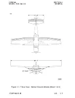
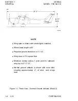
Страница 11: ...CESSNA SECTION 1 MODEL 172S NAV III GENERAL Figure 1 1 Three View Normal Ground Attitude Sheet 1 of 2 172SPHAUS 00 U S 1 3 ...

Страница 12: ...hown with strobe lights installed f Wheel base length is 65 f Propeller ground clearance is 11 1 4 f Wing area is 174 square feet f Minimum turning radius pivot point to outboard wing tip is 27 5 1 2 f Normal ground attitude is shown with nose strut showing approximately 2 of strut and wings level 1 4 U S 172SPHAUS 00 ...

Страница 13: ...ycoming Engine Model Number IO 360 L2A Engine Type Normally aspirated direct drive air cooled horizontally opposed fuel injected four cylinder engine with 360 cu in displacement Horsepower Rating and Engine Speed 180 rated BHP at 2700 RPM PROPELLER Propeller Manufacturer McCauley Propeller Systems Propeller Model Number 1A170E JHA7660 Number of Blades 2 Propeller Diameter 76 inches Propeller Type ...

Страница 14: ... Left or Right position Refer to Figure 1 1 for normal ground attitude dimensions OIL Oil Specification MIL L 6082 or SAE J1966 Aviation Grade Straight Mineral Oil Used when the airplane was delivered from the factory and should be used to replenish the supply during the first 25 hours This oil should be drained and the filter changed after the first 25 hours of operation Refill the engine with MI...

Страница 15: ...t Normal Category 2550 lbs Utility Category 2200 lbs Landing Weight Normal Category 2550 lbs Utility Category 2200 lbs Continued Next Page Temperature MIL L 6082 or SAE J1966 Straight Mineral Oil SAE Grade MIL L 22851 or SAE J1899 Ashless Dispersant SAE Grade Above 27 C 80 F 60 15W 50 20W 50 or 60 Above 16 C 60 F 50 40 or 50 1 C 30 F to 32 C 90 F 40 40 18 C 0 F to 21 C 70 F 30 30 40 or 20W 40 Belo...

Страница 16: ... this category the rear seat must not be occupied and the baggage compartment must be empty STANDARD AIRPLANE WEIGHTS Standard Empty Weight 1663 lbs Maximum Useful Load Normal Category 895 lbs Maximum Useful Load Utility Category 545 lbs CABIN AND ENTRY DIMENSIONS Detailed dimensions of the cabin interior and entry door openings are illustrated in Section 6 BAGGAGE SPACE AND ENTRY DIMENSIONS Dimen...

Страница 17: ...essing the airframe VFE Maximum Flap Extended Speed is the highest speed permissible with wing flaps in a prescribed extended position VNO Maximum Structural Cruising Speed is the speed that should not be exceeded except in smooth air then only with caution VNE Never Exceed Speed is the speed limit that may not be exceeded at any time VS Stalling Speed or the minimum steady flight speed is the min...

Страница 18: ...ring a full RPM throttle engine runup when the airplane is on the ground and stationary MAP Manifold Absolute Pressure is the absolute pressure measured in the engine induction system MAP is measured in units of inches of mercury inHG Lean Decreased proportion of fuel in the fuel air mixture Mixture supplied to the engine As air density decreases the amount of fuel required by the engine decreases...

Страница 19: ...f the crosswind component for which adequate Crosswind control of the airplane during takeoff and landing Velocity was actually demonstrated during certification tests The value shown is not considered to be limiting Usable Fuel Usable Fuel is the fuel available for flight planning Unusable Unusable Fuel is the quantity of fuel that can not be Fuel safely used in flight GPH Gallons Per Hour is the...

Страница 20: ...s the point at which an airplane or Gravity equipment would balance if suspended Its distance C G from the reference datum is found by dividing the total moment by the total weight of the airplane C G Center of Gravity Arm is the arm obtained by Arm adding the airplane s individual moments and dividing the sum by the total weight C G Center of Gravity Limits are the extreme center of Limits gravit...

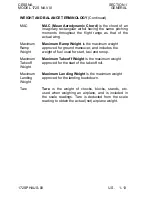
Страница 21: ...ground maneuver and includes the Weight weight of fuel used for start taxi and runup Maximum Maximum Takeoff Weight is the maximum weight Takeoff approved for the start of the takeoff roll Weight Maximum Maximum Landing Weight is the maximum weight Landing approved for the landing touchdown Weight Tare Tare is the weight of chocks blocks stands etc used when weighing an airplane and is included in...

Страница 22: ... convert U S measurement supplied with the Pilot s Operating Handbook into metric and imperial measurements The standard followed for measurement units shown is the National Institute of Standards Technology NIST Publication 811 Guide for the Use of the International System of Units SI Refer to the following pages for these charts 1 14 U S 172SPHAUS 00 ...

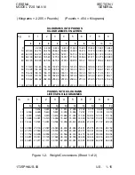
Страница 23: ... 26 100 220 46 222 67 224 87 227 08 229 28 231 49 233 69 235 90 238 10 240 30 POUNDS INTO KILOGRAMS LIVRES EN KILOGRAMMES lb 0 1 2 3 4 5 6 7 8 9 kg kg kg kg kg kg kg kg kg kg 0 0 454 0 907 1 361 1 814 2 268 2 722 3 175 3 629 4 082 10 4 536 4 990 5 443 5 897 6 350 6 804 7 257 7 711 8 165 8 618 20 9 072 9 525 9 979 10 433 10 886 11 340 11 793 12 247 12 701 13 154 30 13 608 14 061 14 515 14 969 15 42...

Страница 24: ...SECTION 1 CESSNA GENERAL MODEL 172S NAV III Figure 1 2 Weight Conversions Sheet 2 1 16 U S 172SPHAUS 00 ...

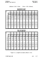
Страница 25: ...94 31 699 32 004 32 309 32 614 32 918 33 223 METERS INTO FEET METRES EN PIEDS m 0 1 2 3 4 5 6 7 8 9 feet feet feet feet feet feet feet feet feet feet 0 3 281 6 562 9 842 13 123 16 404 19 685 22 956 26 247 29 528 10 32 808 36 089 39 370 42 651 45 932 49 212 52 493 55 774 59 055 62 336 20 65 617 68 897 72 178 75 459 78 740 82 021 85 302 88 582 91 863 95 144 30 98 425 101 71 104 99 108 27 111 55 114 ...

Страница 26: ...SECTION 1 CESSNA GENERAL MODEL 172S NAV III Figure 1 3 Length Conversions Sheet 2 1 18 U S 172SPHAUS 00 ...

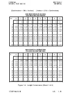
Страница 27: ...6 100 39 370 39 764 40 157 40 551 40 945 41 339 41 732 42 126 42 520 42 913 INCHES INTO CENTIMETERS POUCES EN CENTIMETRES in 0 1 2 3 4 5 6 7 8 9 cm cm cm cm cm cm cm cm cm cm 0 2 54 5 08 7 62 10 16 12 70 15 24 17 78 20 32 22 96 10 25 40 27 94 30 48 33 02 35 56 38 10 40 64 43 18 45 72 48 26 20 50 80 53 34 55 88 58 42 60 96 63 50 66 04 68 58 71 12 73 66 30 76 20 78 74 81 28 83 82 86 36 88 90 91 44 9...

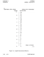
Страница 28: ...SECTION 1 CESSNA GENERAL MODEL 172S NAV III Figure 1 4 Length Conversions Sheet 2 1 20 U S 172SPHAUS 00 ...

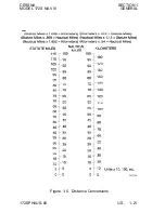
Страница 29: ...CESSNA SECTION 1 MODEL 172S NAV III GENERAL Figure 1 5 Distance Conversions 172SPHAUS 00 U S 1 21 ...

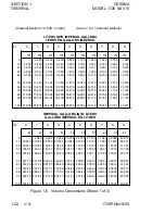
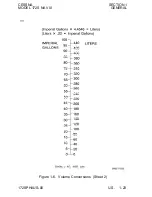
Страница 30: ...2 878 23 098 23 318 23 537 23 757 23 977 IMPERIAL GALLONS INTO LITERS GALLONS IMPERIAL EN LITRES IG 0 1 2 3 4 5 6 7 8 9 Lt Lt Lt Lt Lt Lt Lt Lt Lt Lt 0 4 546 9 092 13 638 18 184 22 730 27 276 31 822 36 368 40 914 10 45 460 50 006 54 552 59 097 63 643 68 189 72 735 77 281 81 827 86 373 20 90 919 95 465 100 01 104 56 109 10 113 65 118 20 122 74 127 29 131 83 30 136 38 140 93 145 47 150 02 154 56 159...

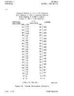
Страница 31: ...CESSNA SECTION 1 MODEL 172S NAV III GENERAL Figure 1 6 Volume Conversions Sheet 2 172SPHAUS 00 U S 1 23 ...

Страница 32: ...SECTION 1 CESSNA GENERAL MODEL 172S NAV III Figure 1 6 Volume Conversions Sheet 3 1 24 U S 172SPHAUS 00 ...

Страница 33: ...CESSNA SECTION 1 MODEL 172S NAV III GENERAL Figure 1 7 Temperature Conversions 172SPHAUS 00 U S 1 25 ...

Страница 34: ...SECTION 1 CESSNA GENERAL MODEL 172S NAV III Figure 1 8 Hectopascals to Inches Mercury PRESSURE CONVERSION HECTOPASCALS MILLIBARS TO INCHES MERCURY inHG 1 26 U S 172SPHAUS 00 ...

Страница 35: ...CESSNA SECTION 1 MODEL 172S NAV III GENERAL Figure 1 9 Volume to Weight Conversion 172SPHAUS 00 U S 1 27 ...

Страница 36: ...SECTION 1 CESSNA GENERAL MODEL 172S NAV III Figure 1 10 Quick Conversions 1 28 U S 172SPHAUS 00 ...

Страница 37: ...y Limits 2 8 Normal Category 2 8 Utility Category 2 9 Maneuver Limits 2 9 Normal Category 2 9 Utility Category 2 10 Flight Load Factor Limits 2 11 Normal Category 2 11 Utility Category 2 11 Kinds Of Operation Limits 2 11 Kinds Of Operations Equipment List 2 12 Fuel Limitations 2 16 Flap Limitations 2 16 System Limitations 2 17 Aux Audio System 2 17 12V Power System 2 17 G1000 Limitations 2 18 GPS ...

Страница 38: ......

Страница 39: ...Section 9 of this Pilot s Operating Handbook for amended operating limitations operating procedures performance data and other necessary information for airplanes equipped with specific options f The airspeeds listed in Figure 2 1 Airspeed Limitations and Figure 2 2 Airspeed Indicator Markings are based on Airspeed Calibration data shown in Section 5 with the normal static source If the alternate ...

Страница 40: ...NE Never Exceed Speed 160 163 Do not exceed this speed in any operation VNO Maximum Structural Cruising Speed 126 129 Do not exceed this speed except in smooth air and then only with caution VA Maneuvering Speed 2550 Pounds 2200 Pounds 1900 Pounds 102 95 88 105 98 90 Do not make full or abrupt control movements above this speed VFE Maximum Flap Extended Speed Flaps10 Flaps10 to FULL 107 85 110 85 ...

Страница 41: ...rspeed warning White Arc 40 85 Full Flap Operating Range Lower limit is maximum weight VS0 in landing configuration Upper limit is maximum speed permissible with flaps extended Green Arc 48 129 Normal Operating Range Lower limit is maximum weight VS1 at most forward C G with flaps retracted Upper limit is maximum structural cruising speed Yellow Arc 129 163 Operations must be conducted with cautio...

Страница 42: ...m Oil Temperature 245 F 118 C Oil Pressure Minimum 20 PSI Oil Pressure Maximum 115 PSI Fuel Grade See Fuel Limitations Oil Grade Specification MIL L 6082 or SAE J1966 Aviation Grade Straight Mineral Oil or MIL L 22851 or SAE J1899 Ashless Dispersant Oil Oil must comply with the latest revision and or supplement for Textron Lycoming Service Instruction No 1014 Propeller Manufacturer McCauley Propel...

Страница 43: ... limit is lower end of red arc Figure 2 3 INSTRUMENT RED LINE MIN RED ARC LWR YELLOW ARC GREEN ARC NORMAL OPERATING RANGE RED ARC UPR Tachometer Sea Level 5000 Feet 10 000 Feet RPM 2100 to 2500 2100 to 2600 2100 to 2700 RPM 2700 to 3000 Cylinder Head Temperature 200 to 500 F Oil Temperature 100 to 245 F 245 to 250 F Oil Pressure 0 to 20 PSI 50 to 90 PSI 115 to 120 PSI Fuel Quantity 0 1 5 Gallons U...

Страница 44: ...120 lbs UTILITY CATEGORY Maximum Ramp Weight 2208 POUNDS Maximum Takeoff Weight 2200 POUNDS Maximum Landing Weight 2200 POUNDS Maximum Weight in Baggage Compartment In the utility category the baggage compartment must be empty and rear seat must not be occupied CENTER OF GRAVITY LIMITS NORMAL CATEGORY Center of Gravity Range Forward 35 0 inches aft of datum at 1950 pounds or less with straight lin...

Страница 45: ...ORY This airplane is certificated in both the normal and utility category The normal category is applicable to aircraft intended for non aerobatic operations These include any maneuvers incidental to normal flying stalls except whip stalls lazy eights chandelles and turns in which the angle of bank is not more than 60 NORMAL CATEGORY MANEUVERS AND RECOMMENDED ENTRY SPEED Chandelles 105 KNOTS Lazy ...

Страница 46: ...S AND RECOMMENDED ENTRY SPEED Chandelles 105 KNOTS Lazy Eights 105 KNOTS Steep Turns 95 KNOTS Spins Slow Deceleration Stalls Except Whip Stalls Slow Deceleration Abrupt use of the controls is prohibited above 98 KNOTS Aerobatics that may impose high loads should not be attempted The important thing to bear in mind in flight maneuvers is that the airplane is clean in aerodynamic design and will bui...

Страница 47: ... design load factors are 150 of the above and in all cases the structure meets or exceeds design loads KINDS OF OPERATION LIMITS The Cessna 172S Nav III airplane is approved for day and night VFR and IFR operations Flight into known icing conditions is prohibited The minimum equipment for approved operations required under the Operating Rules are defined by 14 CFR Part 91 and 14 CFR Part 135 as ap...

Страница 48: ...IND OF OPERATION V F R D A Y V F R N I G H T I F R D A Y I F R N I G H T COMMENTS PLACARDS AND MARKINGS 172S Nav III POH AFM 1 1 1 1 Accessible to pilot in flight Garmin G1000TM Cockpit Reference Guide 1 1 1 1 Accessible to pilot in flight AIR CONDITIONING 1 Forward Avionics Fan 2 PFD Fan 3 MFD Fan 4 Aft Avionics Fan 1 0 0 1 1 0 0 1 1 0 0 1 1 0 0 1 AUTOFLIGHT 1 Bendix King KAP 140 POH Supplement 0...

Страница 49: ...ccupants FLIGHT CONTROLS 1 Flap Position Indicator 2 Flap Motor 3 Elevator Trim System 4 Elevator Trim Indicator 1 1 1 1 1 1 1 1 1 1 1 1 1 1 1 1 FUEL SYSTEM 1 Electric Fuel Pump 2 Fuel Quantity Indicator LH Tank 3 Fuel Quantity Indicator RH Tank 1 1 1 1 1 1 1 1 1 1 1 1 ICE AND RAIN PROTECTION 1 Alternate Static Air Source 2 Alternate Induction Air System 0 0 0 0 1 1 1 1 INDICATING RECORDING SYSTEM...

Страница 50: ...R N I G H T I F R D A Y I F R N I G H T COMMENTS LIGHTING 1 PFD Bezel Lighting 2 PFD Backlighting 3 MFD Bezel Lighting 4 MFD Backlighting 5 Switch and Circuit Breaker Panel Lighting 6 Airspeed Indicator Standby Internal Lighting 7 Altimeter Standby Internal Lighting 8 Non stabilized Magnetic Compass Internal Lighting 9 Attitude Indicator Vacuum Internal Lighting 10 Cockpit Flood Light 11 Aircraft ...

Страница 51: ...c Compass 11 VHF Navigation Radio VOR LOC GS 12 GPS Receiver Navigator 13 Marker Beacon Receiver 14 Blind Altitude Encoder 15 Clock 1 0 1 0 0 0 0 0 0 1 0 0 0 A R 0 1 0 1 0 0 0 0 0 0 1 0 0 0 A R 0 1 1 1 1 0 1 1 1 1 1 A R A R A R 1 1 1 1 1 1 0 1 1 1 1 1 A R A R A R 1 1 As Required Per Procedure As Required Per Procedure As Required Per Procedure As Required Per Procedure VACUUM 1 Engine driven Vacuu...

Страница 52: ...mal ground attitude definition Takeoff and land with the fuel selector valve handle in the BOTH position Maximum slip or skid duration with one tank dry 30 seconds Operation on either LEFT or RIGHT tank limited to level flight only With 1 4 tank or less prolonged uncoordinated flight is prohibited when operating on either left or right tank Fuel remaining in the tank after the fuel quantity indica...

Страница 53: ...ortable electronic device s will not cause interference with the navigation or communication system of the airplane 12V POWER SYSTEM The 12 Volt Power System POWER OUTLET 12V 10A is not certified for supplying power to flight critical communications or navigation devices Use of the 12 Volt Power System is prohibited during takeoff and landing Use of the 12 Volt Power System is prohibited under IFR...

Страница 54: ... of the pilot to see and maneuver to avoid traffic Use of the TERRAIN PROXIMITY information for primary terrain avoidance is prohibited The TERRAIN PROXIMITY map is intended only to enhance situational awareness It is the pilot s responsibility to provide terrain clearance at all times Navigation using the G1000 is not authorized north of 70 North latitude or south of 70 South latitude due to unsu...

Страница 55: ...eceiver Autonomous Integrity Monitoring RAIM capability for TSO C129a non WAAS equipment e g oceanic operations U S RNAV routes European BRNAV and PRNAV etc the Garmin WAAS Fault Detection Exclusion Prediction program 006 A0154 01 or later approved version should be used to confirm the availability of RAIM for the intended route and time of flight Generic prediction tools do not provide an accurat...

Страница 56: ...s which must be complied with when operating this airplane in this category or in the Utility Category are contained in the Pilot s Operating Handbook and FAA Approved Airplane Flight Manual Normal Category No acrobatic maneuvers including spins approved Utility Category No acrobatic maneuvers approved except those listed in the Pilot s Operating Handbook Baggage compartment and rear seat must not...

Страница 57: ... S GAL USABLE TO BOTTOM OF FILLER INDICATOR TAB 4 On flap control indicator UP to 10 110 KIAS Partial flap range with blue color code also mechanical detent at 10 10 to FULL 85 KIAS White color code also mechanical detent at 20 TAKEOFF BOTH ALL FLIGHT LANDING 53 0 GAL ATTITUDES FUEL SELECTOR LEFT RIGHT 26 5 GAL 26 5 GAL LEVEL LEVEL FLIGHT FLIGHT ONLY ONLY Continued Next Page FAA APPROVED I172SPHAU...

Страница 58: ...R LATCH MAXIMUM 120 POUNDS COMBINED FOR ADDITIONAL LOADING INSTRUCTIONS SEE WEIGHT AND BALANCE DATA 6 A calibration card must be provided to indicate the accuracy of the magnetic compass in 30 increments 7 On the oil filler cap 8 On control lock 9 Above the PFD OIL 8 QTS CAUTION CONTROL LOCK REMOVE BEFORE STARTING ENGINE MANEUVERING SPEED 105 KIAS Continued Next Page FAA APPROVED I2 22 U S 172SPHA...

Страница 59: ...nstrument panel SMOKING PROHIBITED EMERGENCY LOCATOR TRANSMITTER INSTALLED AFT OF THIS PARTITION MUST BE SERVICED IN ACCORDANCE WITH FAR PART 91 207 13 Near the center overhead light control Flood Light CAUTION 24 VOLTS D C THIS AIRCRAFT IS EQUIPPED WITH ALTERNATOR AND A NEGATIVE GROUND SYSTEM OBSERVE PROPER POLARITY REVERSE POLARITY WILL DAMAGE ELECTRICAL COMPONENTS FAA APPROVED I172SPHAUS 04 U S...

Страница 60: ......

Страница 61: ...Takeoff 3 6 Engine Failure During Flight Restart Procedures 3 6 FORCED LANDINGS 3 7 Emergency Landing Without Engine Power 3 7 Precautionary Landing With Engine Power 3 8 Ditching 3 8 FIRES 3 9 During Start On Ground 3 9 Engine Fire In Flight 3 10 Electrical Fire In Flight 3 10 Cabin Fire 3 11 Wing Fire 3 11 ICING 3 12 Inadvertent Icing Encounter During Flight 3 12 Static Source Blockage Erroneous...

Страница 62: ...17 LOW VOLTS Annunciator Comes On or Does Not Go Off at Higher RPM 3 17 AIR DATA SYSTEM FAILURE 3 19 Red X PFD Airspeed Indicator 3 19 Red X PFD Altitude Indicator 3 19 ATTITUDE AND HEADING REFERENCE SYSTEM AHRS FAILURE 3 20 Red X PFD Attitude Indicator 3 20 Red X Horizontal Situation Indicator HSI 3 20 DISPLAY COOLING ADVISORY 3 20 PFD1 Cooling or MFD1 Cooling Annunciator s 3 20 VACUUM SYSTEM FAI...

Страница 63: ...y From Spiral Dive In The Clouds AHRS FAILED 3 29 Inadvertent Flight Into Icing Conditions 3 29 Static Source Blocked 3 30 Spins 3 30 Rough Engine Operation Or Loss Of Power 3 31 Spark Plug Fouling 3 31 Magneto Malfunction 3 31 Idle Power Engine Roughness 3 31 Engine Driven Fuel Pump Failure 3 32 Excessive Fuel Vapor 3 32 Low Oil Pressure 3 32 Electrical Power Supply System Malfunctions 3 33 Exces...

Страница 64: ......

Страница 65: ...nes described in this section should be considered and applied as necessary to correct the problem In any emergency situation the most important task is continued control of the airplane and maneuver to execute a successful landing Emergency procedures associated with optional or supplemental equipment are found in Section 9 Supplements AIRSPEEDS FOR EMERGENCY OPERATION ENGINE FAILURE AFTER TAKEOF...

Страница 66: ... Switch OFF 7 MASTER Switch ALT and BAT OFF ENGINE FAILURE IMMEDIATELY AFTER TAKEOFF 1 Airspeed 70 KIAS Flaps UP 65 KIAS Flaps 10 FULL 2 Mixture Control IDLE CUTOFF pull full out 3 FUEL SHUTOFF Valve OFF pull full out 4 MAGNETOS Switch OFF 5 Wing Flaps AS REQUIRED FULL recommended 6 STBY BATT Switch OFF 7 MASTER Switch ALT and BAT OFF 8 Cabin Door UNLATCH 9 Land STRAIGHT AHEAD ENGINE FAILURE DURIN...

Страница 67: ...If the indicated fuel flow FFLOW GPH immediately drops to zero a sign of failure of the engine driven fuel pump return the FUEL PUMP switch to the ON position FORCED LANDINGS EMERGENCY LANDING WITHOUT ENGINE POWER 1 Pilot and Passenger Seat Backs MOST UPRIGHT POSITION 2 Seats and Seat Belts SECURE 3 Airspeed 70 KIAS Flaps UP 65 KIAS Flaps 10 FULL 4 Mixture Control IDLE CUTOFF pull full out 5 FUEL ...

Страница 68: ... 12 Mixture Control IDLE CUTOFF pull full out 13 MAGNETOS Switch OFF 14 Brakes APPLY HEAVILY DITCHING 1 Radio TRANSMIT MAYDAY on 121 5 MHz Give location intentions and SQUAWK 7700 2 Heavy Objects in baggage area SECURE OR JETTISON if possible 3 Pilot and Passenger Seat Backs MOST UPRIGHT POSITION 4 Seats and Seat Belts SECURE 5 Wing Flaps 20 FULL 6 Power ESTABLISH 300 FT MIN DESCENT AT 55 KIAS NOT...

Страница 69: ...nutes 3 Engine SHUTDOWN and inspect for damage IF ENGINE FAILS TO START 2 Throttle Control FULL push full in 3 Mixture Control IDLE CUTOFF pull full out 4 MAGNETOS Switch START continue cranking 5 FUEL SHUTOFF Valve OFF pull full out 6 FUEL PUMP Switch OFF 7 MAGNETOS Switch OFF 8 STBY BATT Switch OFF 9 MASTER Switch ALT and BAT OFF 10 Engine SECURE 11 Parking Brake RELEASE 12 Fire Extinguisher OBT...

Страница 70: ...provide an incombustible mixture 7 Forced Landing EXECUTE Refer to EMERGENCY LANDING WITHOUT ENGINE POWER ELECTRICAL FIRE IN FLIGHT 1 STBY BATT Switch OFF 2 MASTER Switch ALT and BAT OFF 3 Vents Cabin Air Heat CLOSED 4 Fire Extinguisher ACTIVATE if available 5 AVIONICS Switch BUS 1 and BUS 2 OFF 6 All Other Switches except MAGNETOS switch OFF WARNING AFTER THE FIRE EXTINGUISHER HAS BEEN USED MAKE ...

Страница 71: ...Vents Cabin Air Heat CLOSED to avoid drafts 4 Fire Extinguisher ACTIVATE if available WARNING AFTER THE FIRE EXTINGUISHER HAS BEEN USED MAKE SURE THAT THE FIRE IS EXTINGUISHED BEFORE EXTERIOR AIR IS USED TO REMOVE SMOKE FROM THE CABIN 5 Vents Cabin Air Heat OPEN When sure that fire is completely extinguished 6 Land the airplane as soon as possible to inspect for damage WING FIRE 1 LAND and TAXI Li...

Страница 72: ... build up select a suitable off airport landing site 6 With an ice accumulation of 0 25 inch or more on the wing leading edges be prepared for significantly higher power requirements higher approach and stall speeds and a longer landing roll 7 Leave wing flaps retracted With a severe ice build up on the horizontal tail the change in wing wake airflow direction caused by wing flap extension could r...

Страница 73: ... Section 5 Figure 5 1 Sheet 2 Airspeed Calibration Alternate Static Source correction chart EXCESSIVE FUEL VAPOR FUEL FLOW STABILIZATION PROCEDURES If flow fluctuations of 1 GPH or more or power surges occur 1 FUEL PUMP Switch ON 2 Mixture Control ADJUST As necessary for smooth engine operation 3 Fuel Selector Valve SELECT OPPOSITE TANK if vapor symptoms continue 4 FUEL PUMP Switch OFF after fuel ...

Страница 74: ...ong as possible with aileron control 4 Directional Control MAINTAIN Using brake on good wheel as required LANDING WITH A FLAT NOSE TIRE 1 Approach NORMAL 2 Wing Flaps AS REQUIRED 85 to 110 KIAS Flaps Up 10 Below 85 KIAS Flaps 10 FULL 3 Touchdown ON MAINS Hold nosewheel off the ground as long as possible 4 When nosewheel touches down maintain full up elevator as airplane slows to stop 3 14 U S 172S...

Страница 75: ...g STROBE Lights OFF h CABIN PWR 12V OFF NOTE f The Main Battery supplies electrical power to the Main and Essential Buses until M BUS VOLTS decreases below 20 volts When M BUS VOLTS falls below 20 volts the Standby Battery System will automatically supply electrical power to the Essential Bus for at least 30 minutes f Select COM1 MIC and NAV1 on the audio panel and tune to the active frequency bef...

Страница 76: ...will be inoperative once AVIONICS BUS 2 is selected to OFF NOTE When AVIONICS BUS 2 is set to OFF the following items will not operate KAP 140 Autopilot GMA 1347 Audio Panel COMM 2 NAV 2 GTX 33 Transponder GDU 1040 MFD k AVIONICS Switch BUS 2 OFF KEEP ON if in clouds 3 Land as soon as practical NOTE Make sure a successful landing is possible before extending flaps The flap motor is a large electri...

Страница 77: ...MES ON OR DOES NOT GO OFF AT HIGHER RPM 1 MASTER Switch ALT Only OFF 2 Alternator Circuit Breaker ALT FIELD CHECK IN 3 MASTER Switch ALT and BAT ON 4 Low Voltage Annunciator LOW VOLTS CHECK OFF 5 M BUS VOLTS CHECK 27 5 V minimum 6 M BAT AMPS CHECK CHARGING IF LOW VOLTS ANNUNCIATOR REMAINS ON 7 MASTER Switch ALT Only OFF 8 Electrical Load REDUCE IMMEDIATELY as follows a AVIONICS Switch BUS 1 OFF b ...

Страница 78: ... minutes f Select COM1 MIC and NAV1 on the audio panel and tune to the active frequency before setting AVIONICS BUS 2 to OFF If COM2 MIC and NAV2 are selected when AVIONICS BUS 2 is set to OFF the COM and NAV radios cannot be tuned i COM1 and NAV1 TUNE TO ACTIVE FREQUENCY j COM1 MIC and NAV1 SELECT COM2 MIC and NAV2 will be inoperative once AVIONICS BUS 2 is selected to OFF NOTE When AVIONICS BUS ...

Страница 79: ...ATA SYSTEM FAILURE RED X PFD AIRSPEED INDICATOR 1 ADC AHRS Circuit Breakers CHECK IN ESS BUS and AVN BUS 1 If open reset close circuit breaker If circuit breaker opens again do not reset 2 Standby Airspeed Indicator USE FOR AIRSPEED INFORMATION RED X PFD ALTITUDE INDICATOR 1 ADC AHRS Circuit Breakers CHECK IN ESS BUS and AVN BUS 1 If open reset close circuit breaker If circuit breaker opens again ...

Страница 80: ...1 If open reset close circuit breaker If circuit breaker opens again do not reset 2 Non Stabilized Magnetic Compass USE FOR HEADING INFORMATION DISPLAY COOLING ADVISORY PFD1 COOLING OR MFD1 COOLING ANNUNCIATOR S 1 Cabin Heat CABIN HT REDUCE minimum preferred 2 Forward Avionics Fan CHECK feel for airflow from screen on glareshield IF FORWARD AVIONICS FAN HAS FAILED 3 STBY BATT Switch OFF unless nee...

Страница 81: ...RING FLIGHT OR THE GYRO FLAG IS SHOWN ON THE STANDBY ATTITUDE INDICATOR THE STANDBY ATTITUDE INDICATOR MUST NOT BE USED FOR ATTITUDE INFORMATION HIGH CARBON MONOXIDE CO LEVEL ANNUNCIATOR if installed CO LVL HIGH ANNUNCIATOR COMES ON 1 CABIN HT Knob OFF push full in 2 CABIN AIR Knob ON pull full out 3 Cabin Vents OPEN 4 Cabin Windows OPEN 163 KIAS maximum windows open speed CO LVL HIGH ANNUNCIATOR ...

Страница 82: ... will provide added safety after a failure of this type If an engine failure occurs immediately after takeoff in most cases the landing should be planned straight ahead with only small changes in direction to avoid obstructions Altitude and airspeed are seldom sufficient to execute the 180 gliding turn necessary to return to the runway The checklist procedures assume that adequate time exists to s...

Страница 83: ...CESSNA SECTION 3 MODEL 172S NAV III EMERGENCY PROCEDURES MAXIMUM GLIDE Figure 3 1 I172SPHAUS 01 U S 3 23 ...

Страница 84: ...e at touchdown Transmit Mayday messages on 121 5 MHz giving location and intentions and squawk 7700 Avoid a landing flare because of the difficulty in judging height over a water surface The checklist assumes the availability of power to make a precautionary water landing If power is not available use of the airspeeds noted with minimum flap extension will provide a more favorable attitude for a p...

Страница 85: ... engine flooding and subsequent collection of fuel on the parking ramp as the excess fuel drains overboard from the intake manifolds This is sometimes experienced in difficult starts in cold weather where engine preheat service is not available If this occurs the airplane should be pushed away from the fuel puddle before another engine start is attempted Otherwise there is a possibility of raw fue...

Страница 86: ...dicators the pilot must rely on the standby attitude indicator and non stabilized magnetic compass for attitude and heading information The KAP 140 Autopilot will not operate in HDG mode without AHRS input With a valid GPS or NAV input and an operating turn coordinator the autopilot will operate in NAV APR or REV modes Autopilot altitude hold and vertical speed operating modes are independent of A...

Страница 87: ...aintain altitude and 15 bank angle Continue the turn for 60 seconds then roll back to level flight 3 When the compass card becomes sufficiently stable check the accuracy of the turn by verifying that the compass heading approximates the reciprocal of the original heading 4 If necessary adjust the heading by keeping the wings level and using the rudder to make skidding turns the compass will read m...

Страница 88: ...ass heading and make minor corrections to hold an approximate course The autopilot may be engaged in ROL mode to keep the wings level and VS mode to control rate of descent Before descending into the clouds prepare for a stabilized descent as follows 1 Apply full rich mixture 2 Turn pitot heat on 3 Set power for a 500 to 800 feet per minute rate of descent 4 Set the elevator trim for a stabilized ...

Страница 89: ... DESCENT THROUGH THE CLOUDS procedure 8 Upon breaking out of clouds resume normal cruising flight INADVERTENT FLIGHT INTO ICING CONDITIONS Flight into icing conditions is prohibited and extremely dangerous An inadvertent encounter with these conditions can be resolved using the checklist procedures The best action is to turn back or change altitude to escape icing conditions Set the PITOT HEAT swi...

Страница 90: ...LERONS IN NEUTRAL POSITION 3 APPLY AND HOLD FULL RUDDER OPPOSITE TO THE DIRECTION OF ROTATION 4 JUST AFTER THE RUDDER REACHES THE STOP MOVE THE CONTROL WHEEL BRISKLY FORWARD FAR ENOUGH TO BREAK THE STALL Full down elevator may be required at aft center of gravity loadings to assure optimum recoveries 5 HOLD THESE CONTROL INPUTS UNTIL ROTATION STOPS Premature relaxation of the control inputs may ex...

Страница 91: ...NETOS switch from BOTH to the L and R switch positions will identify which magneto is malfunctioning Select different power settings and enrichen the mixture to determine if continued operation on BOTH magnetos is possible If not change to the good magneto and continue to the nearest airport for repairs IDLE POWER ENGINE ROUGHNESS As Required by AD 2001 06 17 Paragraph d 3 An excessively rich idle...

Страница 92: ... flow indicator FFLOW GPH fluctuations greater than 1 gal hr This condition with leaner mixtures or with larger fluctuations can result in power surges and if not corrected may cause power loss To slow vapor formation and stabilize fuel flow on the ground or in the air set the FUEL PUMP switch to the ON position and adjust the mixture as required for smooth engine operation If vapor symptoms conti...

Страница 93: ...n wiring is most likely the cause of alternator failures although other factors could cause the problem A defective alternator control unit ACU can also cause malfunctions Problems of this nature constitute an electrical emergency and should be dealt with immediately Electrical power malfunctions usually fall into two categories excessive rate of charge and insufficient rate of charge The followin...

Страница 94: ...e main battery ammeter and the low voltage annunciator LOW VOLTS will come on The ACU can de energize the alternator due to minor disturbances in the electrical system resulting in a nuisance opening of the ALT FIELD circuit breaker If this happens an attempt should be made to energize the alternator system To energize the alternator system 1 MASTER Switch ALT Only OFF 2 Alternator Circuit Breaker...

Страница 95: ...ystems on the Essential Bus and cannot provide power for transponder XPDR operation Main battery life should be extended when practical for possible later operation of the wing flaps and use of the landing light at night NOTE The LOW VOLTS annunciator can come on when the engine is operated at low RPM with a high electrical load The LOW VOLTS annunciator will usually go off when the engine is oper...

Страница 96: ...ms mentioned above or the CO LVL HIGH warning annunciation comes on when using the cabin heater immediately turn off the cabin heater and preform the emergency items for HIGH CARBON MONOXIDE CO LEVEL When the CO detection system senses a CO level of 50 parts per million PPM by volume or greater the alarm turns on a flashing warning annunciation CO LVL HIGH in the annunciation window on the PFD wit...

Страница 97: ...ennage 4 8 Right Wing Trailing Edge 4 8 Right Wing 4 9 Nose 4 10 Left Wing Leading Edge 4 11 Left Wing 4 11 Left Wing Trailing Edge 4 12 Before Starting Engine 4 12 Starting Engine With Battery 4 12 Starting Engine With External Power 4 14 Before Takeoff 4 16 Takeoff 4 19 Normal Takeoff 4 19 Short Field Takeoff 4 19 Enroute Climb 4 19 Cruise 4 20 Descent 4 20 Before Landing 4 22 Continued Next Pag...

Страница 98: ...ng Engine 4 25 Recommended Starter Duty Cycle 4 26 Leaning For Ground Operations 4 27 Taxiing 4 27 Before Takeoff 4 29 Warm Up 4 29 Magneto Check 4 29 Alternator Check 4 29 Elevator Trim 4 30 Landing Lights 4 30 Takeoff 4 30 Power Check 4 30 Wing Flap Settings 4 31 Crosswind Takeoff 4 31 Enroute Climb 4 32 Cruise 4 32 Leaning Using Exhaust Gas Temperature EGT 4 34 Fuel Savings Procedures for Fligh...

Страница 99: ...39 Spins 4 39 Holding Procedure Turns and Missed Approaches 4 42 Landing 4 46 Normal Landing 4 46 Short Field Landing 4 46 Crosswind Landing 4 47 Balked Landing 4 47 Cold Weather Operation 4 48 Starting 4 48 Winterization Kit 4 49 Hot Weather Operation 4 50 Noise Characteristics And Noise Reduction 4 50 172SPHAUS 03 U S 4 3 4 4 ...

Страница 100: ......

Страница 101: ...hort Field Takeoff Flaps 10 Speed at 50 Feet 56 KIAS ENROUTE CLIMB FLAPS UP Normal Sea Level 75 85 KIAS Normal 10 000 Feet 70 80 KIAS Best Rate of Climb Sea Level 74 KIAS Best Rate of Climb 10 000 Feet 72 KIAS Best Angle of Climb Sea Level 62 KIAS Best Angle of Climb 10 000 Feet 67 KIAS LANDING APPROACH Normal Approach Flaps UP 65 75 KIAS Normal Approach Flaps FULL 60 70 KIAS Short Field Approach ...

Страница 102: ...assist handles will simplify access to the upper wing surfaces for visual checks and refueling operations In cold weather remove even small accumulations of frost ice or snow from wing tail and control surfaces Also make sure that control surfaces contain no internal accumulations of ice or debris Prior to flight check that pitot heater is warm to touch within 30 seconds with battery and pitot hea...

Страница 103: ...S SWITCH WERE ON DO NOT STAND NOR ALLOW ANYONE ELSE TO STAND WITHIN THE ARC OF THE PROPELLER SINCE A LOOSE OR BROKEN WIRE OR A COMPONENT MALFUNCTION COULD CAUSE THE ENGINE TO START 7 MAGNETOS Switch OFF 8 AVIONICS Switch BUS 1 and BUS 2 OFF 9 MASTER Switch ALT and BAT ON 10 Primary Flight Display PFD CHECK Verfiy PFD is ON 11 FUEL QTY L and R CHECK 12 LOW FUEL L and LOW FUEL R Annunciators CHECK V...

Страница 104: ...r Trim Control TAKEOFF position 26 FUEL SELECTOR Valve BOTH 27 ALT STATIC AIR Valve OFF push full in 28 Fire Extinguisher CHECK Verify gage pointer in green arc 2 EMPENNAGE 1 Baggage Door CHECK lock with key 2 Autopilot Static Source if installed CHECK Verify opening is clear 3 Rudder Gust Lock if installed REMOVE 4 Tail Tiedown DISCONNECT 5 Control Surfaces CHECK freedom of movement and security ...

Страница 105: ...ve any additional contaminants to the sampling points Take repeated samples from all fuel drain points until all contamination has been removed If contaminants are still present refer to WARNING below and do not fly airplane NOTE Collect all sampled fuel in a safe container Dispose of the sampled fuel so that it does not cause a nuisance hazard or damage to the environment WARNING IF AFTER REPEATE...

Страница 106: ...l in a safe container Dispose of the sampled fuel so that it does not cause a nuisance hazard or damage to the environment WARNING IF AFTER REPEATED SAMPLING EVIDENCE OF CONTAMINATION STILL EXISTS THE AIRPLANE SHOULD NOT BE FLOWN TANKS SHOULD BE DRAINED AND SYSTEM PURGED BY QUALIFIED MAINTENANCE PERSONNEL ALL EVIDENCE OF CONTAMINATION MUST BE REMOVED BEFORE FURTHER FLIGHT 2 Engine Oil Dipstick Fil...

Страница 107: ...ght and after each refueling If water is observed take further samples until clear and then gently rock wings and lower tail to the ground to move any additional contaminants to the sampling points Take repeated samples from all fuel drain points until all contamination has been removed If contaminants are still present refer to WARNING below and do not fly airplane NOTE Collect all sampled fuel i...

Страница 108: ...LE DAMAGE TO AVIONICS 8 FUEL SELECTOR Valve BOTH 9 FUEL SHUTOFF Valve ON push full in STARTING ENGINE With Battery 1 Throttle Control OPEN 1 4 INCH 2 Mixture Control IDLE CUTOFF pull full out 3 STBY BATT Switch a TEST Hold for 20 seconds verify that green TEST lamp does not go off b ARM Verify that PFD comes on 4 Engine Indicating System CHECK PARAMETERS Verify no red X s through ENGINE page indic...

Страница 109: ...starts 16 Mixture Control ADVANCE smoothly to RICH when engine starts NOTE If the engine is primed too much flooded place the mixture control in the IDLE CUTOFF position open the throttle control 1 2 to full and engage the starter motor START When the engine starts advance the mixture control to the FULL RICH position and retard the throttle control promptly 17 Oil Pressure CHECK Verify that oil p...

Страница 110: ...or CHECK Verify annunciator is shown 9 AVIONICS Switch BUS 1 and BUS 2 OFF 10 MASTER Switch ALT and BAT OFF 11 Propeller Area CLEAR Verify that all people and equipment are at a safe distance from the propeller 12 External Power CONNECT to ground power receptacle 13 MASTER Switch ALT and BAT ON 14 BEACON Light Switch ON 15 M BUS VOLTS CHECK Verify that approximately 28 VOLTS is shown NOTE If engin...

Страница 111: ...ound power Latch external power receptacle door 24 Power INCREASE to approximately 1500 RPM for several minutes to charge battery 25 AMPS M BATT and BATT S CHECK charge positive 26 LOW VOLTS Annunciator CHECK Verify annunciator is not shown 27 Internal Power CHECK a MASTER Switch ALT OFF b TAXI and LANDING Light Switches ON c Throttle Control REDUCE to idle d MASTER Switch ALT and BAT ON e Throttl...

Страница 112: ...installed NOTE There is no connection between the G1000 ALT SEL feature and the KAP 140 autopilot altitude preselect or altitude hold functions G1000 and KAP 140 altitudes are set independently 10 Standby Flight Instruments CHECK 11 Fuel Quantity CHECK Verify level is correct NOTE Flight is not recommended when both fuel quantity indicators are in the yellow arc range 12 Mixture Control RICH 13 FU...

Страница 113: ...equency s SET 22 NAV Frequency s SET 23 FMS GPS Flight Plan AS DESIRED NOTE Check GPS availability on AUX GPS STATUS page No annunciation is provided for loss of GPS2 24 XPDR SET 25 CDI Softkey SELECT NAV source CAUTION THE G1000 HSI SHOWS A COURSE DEVIATION INDICATOR FOR THE SELECTED GPS NAV 1 OR NAV 2 NAVIGATION SOURCE THE G1000 HSI DOES NOT PROVIDE A WARNING FLAG WHEN A VALID NAVIGATION SIGNAL ...

Страница 114: ...ANNUNCIATION WILL BE PROVIDED THE PREVIOUSLY SELECTED MODE SYMBOL SHOWN ON THE AUTOPILOT DISPLAY WILL BE FLASHING TO SHOW THE REVERSION TO ROLL MODE OPERATION IN ROLL MODE THE AUTOPILOT WILL ONLY KEEP THE WINGS LEVEL AND WILL NOT CORRECT THE AIRPLANE HEADING OR COURSE SET THE HDG BUG TO THE CORRECT HEADING AND SELECT THE CORRECT NAVIGATION SOURCE ON THE HSI USING THE CDI SOFTKEY BEFORE ENGAGING TH...

Страница 115: ...fe altitude SHORT FIELD TAKEOFF 1 Wing Flaps 10 2 Brakes APPLY 3 Throttle Control FULL push full in 4 Mixture Control RICH Above 3000 feet pressure altitude lean for maximum RPM 5 Brakes RELEASE 6 Elevator Control SLIGHTLY TAIL LOW 7 Climb Speed 56 KIAS Until all obstacles are cleared 8 Wing Flaps RETRACT SLOWLY When airspeed is more than 60 KIAS ENROUTE CLIMB 1 Airspeed 70 85 KIAS 2 Throttle Cont...

Страница 116: ... IFR DESCENT 1 Power AS DESIRED 2 Mixture ADJUST if necessary to make the engine run smoothly 3 Altimeters a PFD BARO SET b Standby Altimeter SET c KAP 140 Autopilot BARO SET if installed 4 G1000 ALT SEL SET 5 KAP 140 Altitude Preselect SET if installed NOTE There is no connection between the G1000 ALT SEL feature and the KAP 140 autopilot altitude preselect or altitude hold functions G1000 and KA...

Страница 117: ...MODES IF THE HSI NAVIGATION SOURCE IS CHANGED FROM GPS TO NAV1 AUTOMATICALLY OR MANUALLY USING THE CDI SOFTKEY OR MANUALLY FROM NAV2 TO GPS THE CHANGE WILL INTERRUPT THE NAVIGATION SIGNAL TO THE AUTOPILOT AND WILL CAUSE THE AUTOPILOT TO REVERT TO ROLL MODE OPERATION NO WARNING CHIME OR PFD ANNUNCIATION WILL BE PROVIDED THE PREVIOUSLY SELECTED MODE SYMBOL SHOWN ON THE AUTOPILOT DISPLAY WILL BE FLAS...

Страница 118: ...ed 7 CABIN PWR 12V Switch OFF if installed LANDING NORMAL LANDING 1 Airspeed 65 75 KIAS Flaps UP 2 Wing Flaps AS DESIRED UP 10 below 110 KIAS 10 FULL below 85 KIAS 3 Airspeed 60 70 KIAS Flaps FULL 4 Elevator Trim Control ADJUST 5 Touchdown MAIN WHEELS FIRST 6 Landing Roll LOWER NOSEWHEEL GENTLY 7 Braking MINIMUM REQUIRED SHORT FIELD LANDING 1 Airspeed 65 75 KIAS Flaps UP 2 Wing Flaps FULL 3 Airspe...

Страница 119: ...ltitude and 65 KIAS AFTER LANDING 1 Wing Flaps UP SECURING AIRPLANE 1 Parking Brake SET 2 Throttle Control IDLE pull full out 3 Electrical Equipment OFF 4 AVIONICS Switch BUS 1 and BUS 2 OFF 5 Mixture Control IDLE CUTOFF pull full out 6 MAGNETOS Switch OFF 7 MASTER Switch ALT and BAT OFF 8 STBY BATT Switch OFF 9 Control Lock INSTALL 10 FUEL SELECTOR Valve LEFT or RIGHT to prevent crossfeeding betw...

Страница 120: ...ing periodic inspections If the airplane has been waxed or polished check the external static pressure source hole for stoppage If the airplane has been kept in a crowded hangar it should be checked for dents and scratches on wings fuselage and tail surfaces damage to navigation strobe lights and avionics antennas Check for damage to the nosewheel steering system the result of exceeding nosewheel ...

Страница 121: ...ht make sure the fuel tank filler caps are tightly sealed after any fuel system check or servicing Fuel system vents should also be inspected for obstructions ice or water especially after exposure to cold wet weather STARTING ENGINE In cooler weather the engine compartment temperature drops off rapidly following engine shutdown and the injector nozzle lines remain nearly full of fuel In warmer we...

Страница 122: ...nal priming will be necessary After starting if the oil pressure gage does not begin to show pressure within 30 seconds in warmer temperatures and approximately one minute in very cold weather stop the engine and find cause before continued operation Lack of oil pressure can cause serious engine damage NOTE Additional details concerning cold weather starting and operation may be found under COLD W...

Страница 123: ...XIING When taxiing it is important that speed and use of brakes be held to a minimum and that all controls be utilized Refer to Figure 4 2 Taxiing Diagram to maintain directional control and balance Taxiing over loose gravel or cinders should be done at low engine speed to avoid abrasion and stone damage to the propeller tips NOTE The LOW VOLTS annunciator may come on when the engine is operated a...

Страница 124: ... Continued TAXIING DIAGRAM NOTE Strong quartering tail winds require caution Avoid sudden bursts of the throttle and sharp braking when the airplane is in this attitude Use the steerable nosewheel and rudder to maintain direction Figure 4 2 I4 28 U S 172SPHAUS 03 ...

Страница 125: ...difference between magnetos If there is a doubt concerning operation of the ignition system RPM checks at higher engine speeds will usually confirm whether a deficiency exists No RPM drop may indicate a faulty ground to one magneto or magneto timing set in advance of the angle specified ALTERNATOR CHECK Make sure that both the alternator and alternator control unit are operating properly before ni...

Страница 126: ...nuing the takeoff The engine should run smoothly and turn approximately 2300 2400 RPM with mixture leaned to provide maximum RPM Full throttle run ups over loose gravel are especially harmful to propeller tips When takeoffs must be made over a gravel surface advance the throttle slowly This allows the airplane to start rolling before high RPM is developed and the gravel will be blown behind the pr...

Страница 127: ...e If no obstacles are ahead the airplane should be leveled off immediately to accelerate to a higher climb speed When departing a soft field with an aft C G loading the elevator trim control should be adjusted towards the nose down direction to give comfortable control wheel forces during the initial climb CROSSWIND TAKEOFF Takeoffs into strong crosswind conditions normally are performed with the ...

Страница 128: ...and maximum power This speed is 62 KIAS at sea level increasing to 67 KIAS at 10 000 feet This type of climb should be of the minimum duration and engine temperatures should be carefully monitored due to the low climb speed CRUISE Normal cruise is performed between 45 and 75 power The engine RPM and corresponding fuel consumption for various altitudes can be determined by using the data in Section...

Страница 129: ...he use of low power settings are significant factors that should be considered on every trip to reduce fuel consumption In addition to power settings proper leaning techniques also contribute to greater range and are figured into cruise performance tables To achieve the recommended lean mixture fuel consumption figures shown in Section 5 the mixture should be leaned using the exhaust gas temperatu...

Страница 130: ...der EGTs should be within approximately 100 F of each other during normal operations An EGT difference greater than 100 F between cylinders indicates that fuel injection system maintenance is necessary EGT is displayed on the EIS ENGINE and LEAN pages The ENGINE page has a horizontal scale with a temperature indicator inverted triangle with a number representing the cylinder with the highest EGT T...

Страница 131: ...EPEAK F value is negative the mixture can be on the lean side of peak Enrichen the mixture by slowly turning the mixture control clockwise and monitor both fuel flow and EGTs until the leanest cylinder returns to peak EGT EPEAK 0 F or desired setting based on the EGT Table Figure 4 4 EPEAK F values rich of peak will also be a negative value 50 The lean assist system calculation is defined such tha...

Страница 132: ...mixture NOTE f Any change in altitude or power setting will require a change in the recommended lean mixture setting and a recheck of the EGT setting f The EGT indicators take several seconds after a mixture adjustment to start to show exhaust gas temperature changes Finding peak EGT and adjusting the mixture to the applicable setting should take approximately one minute when the adjustments are m...

Страница 133: ...may remain leaned maximum RPM at full throttle for practicing maneuvers such as stalls and slow flight 3 Lean the mixture for maximum RPM during all operations at any altitude including those below 3000 feet when using 75 or less power NOTE f When cruising or maneuvering at 75 or less power the mixture may be further leaned until the EGT indicator peaks and is then enrichened 50 F This is especial...

Страница 134: ... returns 2 Retard the throttle to idle to verify normal engine operation 3 Advance the throttle to 1200 RPM and lean the mixture as described under FUEL SAVINGS PROCEDURES FOR FLIGHT TRAINING OPERATIONS 4 In addition to the above procedures the Auxiliary Fuel Pump may be turned ON with the mixture adjusted as required to aid vapor suppression during ground operations The Auxiliary Fuel Pump should...

Страница 135: ...um weight for both forward and aft C G positions are presented in Section 5 SPINS Intentional spins are approved when the airplane is operated in the utility category Spins with baggage loadings or occupied rear seat s are not approved However before attempting to perform spins several items should be carefully considered to assure a safe flight No spins should be attempted without first having re...

Страница 136: ...eflection is reached almost simultaneously with reaching full aft elevator A slightly greater rate of deceleration than for normal stall entries application of ailerons in the direction of the desired spin and the use of power at the entry will assure more consistent and positive entries to the spin As the airplane begins to spin reduce the power to idle and return the ailerons to neutral Both ele...

Страница 137: ...n of rotation difficult to determine see the turn vector near the index at the top of the Horizontal Situation Indicator HSI Variations in basic airplane rigging or in weight and balance due to installed equipment or right seat occupancy can cause differences in behavior particularly in extended spins These differences are normal and will result in variations in the spin characteristics and in the...

Страница 138: ...her maneuver Holding pattern operations whether in the enroute or the terminal environment require temporary suspension of flight plan execution on reaching the holding waypoint If the holding pattern is part of an Instrument Approach Procedure IAP without an associated Procedure Turn suspend SUSP mode will be invoked automatically by the G1000 FMS GPS on reaching the holding waypoint usually an I...

Страница 139: ...ally or by setting the KAP 140 Autopilot to HDG mode and then setting the HDG bug on the PFD to command the Autopilot to turn to each new heading The KAP 140 Autopilot may be set to APR mode to track the inbound course but must be returned to HDG mode for command through the remainder of the holding pattern NOTE On interception of the inbound course for RNAV GPS Approach holding patterns SUSP will...

Страница 140: ...oaches are managed by the G1000 FMS GPS to provide course guidance and waypoint sequencing through the approach procedure For ILS approaches the G1000 FMS GPS provides course guidance for the KAP 140 to capture the final approach course The G1000 will tune the NAV 1 radio to the applicable facility frequency with identifier and set the course pointer to the final approach course Within approximate...

Страница 141: ...CT THE CORRECT NAVIGATION SOURCE ON THE HSI USING THE CDI SOFTKEY BEFORE ENGAGING THE AUTOPILOT IN ANY OTHER OPERATING MODE Other VHF NAV based Instrument Approach Procedures VOR LOC LOC BC require the pilot to manually tune and identify the NAV facility select the corresponding NAV source on the HSI and set the HSI course pointer to the final approach course See the G1000 Cockpit Reference Guide ...

Страница 142: ... The nosewheel must be lowered to the runway carefully after the speed has diminished to avoid unnecessary nose gear loads This procedure is very important for rough or soft field landings SHORT FIELD LANDING For a short field landing in smooth air conditions approach at 61 KIAS with FULL flaps using enough power to control the glide path Slightly higher approach speeds should be used in turbulent...

Страница 143: ...leron deflection as applicable and occasional braking if necessary The maximum allowable crosswind velocity is dependent upon pilot capability as well as airplane limitations Operation in direct crosswinds of 15 knots has been demonstrated not an operating limitation BALKED LANDING In a balked landing go around climb reduce the flap setting to 20 immediately after full power is applied and climb a...

Страница 144: ...tisfactory flight performance and handling Also control surfaces must be free of any internal accumulations of ice or snow If snow or slush covers the takeoff surface allowance must be made for takeoff distances which will be increasingly extended as the snow or slush depth increases The depth and consistency of this cover can in fact prevent takeoff in many instances STARTING When air temperature...

Страница 145: ...the normal starting procedures However to conserve battery power the beacon light can be left off until the engine is started Use caution to prevent inadvertent forward movement of the airplane during starting when parked on snow or ice NOTE If the engine does not start during the first few attempts or if engine firing diminishes in strength the spark plugs may be frosted over Preheat must be used...

Страница 146: ...d to minimize the effect of airplane noise on the public 1 Pilots operating airplanes under VFR over outdoor assemblies of persons recreational and park areas and other noise sensitive areas should make every effort to fly not less than 2000 feet above the surface weather permitting even though flight at a lower level may be consistent with the provisions of government regulations 2 During departu...

Страница 147: ... Alternate Static Source 5 10 Temperature Conversion Chart 5 11 Stall Speeds at 2550 Pounds 5 12 Crosswind Components 5 13 Short Field Takeoff Distance at 2550 Pounds 5 14 Short Field Takeoff Distance at 2400 Pounds 5 15 Short Field Takeoff Distance at 2200 Pounds 5 16 Maximum Rate Of Climb at 2550 Pounds 5 17 Time Fuel And Distance To Climb at 2550 Pounds 5 18 Cruise Performance 5 19 Range Profil...

Страница 148: ......

Страница 149: ...que fuel metering characteristics engine and propeller condition and air turbulence may account for variations of 10 or more in range and endurance Therefore it is important to utilize all available information to estimate the fuel required for the particular flight and to flight plan in a conservative manner USE OF PERFORMANCE CHARTS Performance data is presented in tabular or graphical form to i...

Страница 150: ...that distances shown are based on the short field technique Conservative distances can be established by reading the chart at the next higher value of weight altitude and temperature For example in this particular sample problem the takeoff distance information presented for a weight of 2550 pounds pressure altitude of 2000 feet and a temperature of 30 C should be used and results in the following...

Страница 151: ...lection for cruise must be determined based on several considerations These include the cruise performance characteristics presented in Figure 5 8 the range profile chart presented in Figure 5 9 and the endurance profile chart presented in Figure 5 10 The relationship between power and range is illustrated by the range profile chart Considerable fuel savings and longer range result when lower powe...

Страница 152: ...ct of a non standard temperature is to increase the time fuel and distance by 10 for each 10 C above standard temperature due to the lower rate of climb In this case assuming a temperature 16 C above standard 16 C 0 C the correction would be 16 C X 10 16 Increase 10 C With this factor included the fuel estimate would be calculated as follows Fuel to climb standard temperature 2 2 Increase due to n...

Страница 153: ...uired for cruise is 3 2 hours X 8 9 gallons hour 28 5 Gallons A 45 minute reserve requires 45 60 X 8 9 gallons hour 6 7 Gallons The total estimated fuel required is as follows Engine start taxi and takeoff 1 4 Climb 2 6 Cruise 28 5 Reserve 6 7 Total fuel required 39 2 Gallons Once the flight is underway ground speed checks will provide a more accurate basis for estimating the time enroute and the ...

Страница 154: ... Ground roll 650 Feet Total distance to clear a 50 foot obstacle 1455 Feet A correction for the effect of wind may be made based on Note 2 of the landing chart using the same procedure as outlined for takeoff DEMONSTRATED OPERATING TEMPERATURE Satisfactory engine cooling has been demonstrated for this airplane with an outside air temperature 23 C above standard This is not to be considered as an o...

Страница 155: ...light or maximum power descent Figure 5 1 Airspeed Calibration Sheet 1 of 2 FLAPS UP KIAS 50 60 70 80 90 100 110 120 130 140 150 160 KCAS 56 62 70 78 87 97 107 117 127 137 147 157 FLAPS 10 KIAS 40 50 60 70 80 90 100 110 KCAS 51 57 63 71 80 89 99 109 FLAPS FULL KIAS 40 50 60 70 80 85 KCAS 50 56 63 72 81 86 172SPHAUS 00 U S 5 9 ...

Страница 156: ...ows closed ventilators closed cabin heater cabin air and defroster on maximum Figure 5 1 Airspeed Calibration Sheet 2 FLAPS UP KIAS 50 60 70 80 90 100 110 120 130 140 150 160 KCAS 56 62 68 76 85 95 105 115 125 134 144 154 FLAPS 10 KIAS 40 50 60 70 80 90 100 110 KCAS 51 55 60 68 77 86 96 105 FLAPS FULL KIAS 40 50 60 70 80 85 KCAS 49 54 61 69 78 83 5 10 U S 172SPHAUS 00 ...

Страница 157: ...CESSNA SECTION 5 MODEL 172S NAV III PERFORMANCE Figure 5 2 Temperature Conversion Chart 172SPHAUS 00 U S 5 11 ...

Страница 158: ... much as 230 feet f KIAS values are approximate Figure 5 3 Stall Speeds FLAP SETTING ANGLE OF BANK 0 KIAS KCAS 30 KIAS KCAS 45 KIAS KCAS 60 KIAS KCAS UP 10 FULL 48 42 40 53 50 48 52 45 43 57 54 52 57 50 48 63 59 57 68 59 57 75 71 68 FLAP SETTING ANGLE OF BANK 0 KIAS KCAS 30 KIAS KCAS 45 KIAS KCAS 60 KIAS KCAS UP 10 FULL 48 43 40 53 51 48 52 46 43 57 55 52 57 51 48 63 61 57 68 61 57 75 72 68 5 12 U...

Страница 159: ...CESSNA SECTION 5 MODEL 172S NAV III PERFORMANCE CROSSWIND COMPONENT Figure 5 4 Crosswind Components 172SPHAUS 00 U S 5 13 ...

Страница 160: ...roll figure Figure 5 5 Short Field Takeoff Distance Sheet 1 of 3 Press Alt In Feet 0 C Grnd Roll Ft Total Ft To Clear 50 Ft Obst 10 C Grnd Roll Ft Total Ft To Clear 50 Ft Obst 20 C Grnd Roll Ft Total Ft To Clear 50 Ft Obst 30 C Grnd Roll Ft Total Ft To Clear 50 Ft Obst 40 C Grnd Roll Ft Total Ft To Clear 50 Ft Obst S L 860 1465 925 1575 995 1690 1070 1810 1150 1945 1000 940 1600 1010 1720 1090 185...

Страница 161: ...round roll figure Figure 5 5 Short Field Takeoff Distance Sheet 2 Press Alt In Feet 0 C Grnd Roll Ft Total Ft To Clear 50 Ft Obst 10 C Grnd Roll Ft Total Ft To Clear 50 Ft Obst 20 C Grnd Roll Ft Total Ft To Clear 50 Ft Obst 30 C Grnd Roll Ft Total Ft To Clear 50 Ft Obst 40 C Grnd Roll Ft Total Ft To Clear 50 Ft Obst S L 745 1275 800 1370 860 1470 925 1570 995 1685 1000 810 1390 875 1495 940 1605 1...

Страница 162: ... the ground roll figure Figure 5 5 Short Field Takeoff Distance Sheet 3 Press Alt In Feet 0 C Grnd Roll Ft Total Ft To Clear 50 Ft Obst 10 C Grnd Roll Ft Total Ft To Clear 50 Ft Obst 20 C Grnd Roll Ft Total Ft To Clear 50 Ft Obst 30 C Grnd Roll Ft Total Ft To Clear 50 Ft Obst 40 C Grnd Roll Ft Total Ft To Clear 50 Ft Obst S L 610 1055 655 1130 705 1205 760 1290 815 1380 1000 665 1145 720 1230 770 ...

Страница 163: ...aned above 3000 feet elevation for maximum RPM Figure 5 6 Maximum Rate of Climb PRESS ALT FT CLIMB SPEED KIAS RATE OF CLIMB FPM 20 C 0 C 20 C 40 C S L 74 855 785 710 645 2000 73 760 695 625 560 4000 73 685 620 555 495 6000 73 575 515 450 390 8000 72 465 405 345 285 10 000 72 360 300 240 180 12 000 72 255 195 135 172SPHAUS 00 U S 5 17 ...

Страница 164: ... for each 10 C above standard temperature f Distances shown are based on zero wind Figure 5 7 Time Fuel and Distance to Climb PRESS ALT FT CLIMB SPEED KIAS RATE OF CLIMB FPM FROM SEA LEVEL TIME IN MIN FUEL USED GAL DIST NM S L 74 730 0 0 0 0 1000 73 695 1 0 4 2 2000 73 655 3 0 8 4 3000 73 620 4 1 2 6 4000 73 600 6 1 5 8 5000 73 550 8 1 9 10 6000 73 505 10 2 2 13 7000 73 455 12 2 6 16 8000 72 410 1...

Страница 165: ...11 1 77 118 10 5 72 117 9 9 2500 78 115 10 6 73 115 9 9 68 115 9 4 2400 69 111 9 6 64 110 9 0 60 109 8 5 2300 61 105 8 6 57 104 8 1 53 102 7 7 2200 53 99 7 7 50 97 7 3 47 95 6 9 2100 47 92 6 9 44 90 6 6 42 89 6 3 4000 2600 83 120 11 1 77 120 10 4 72 119 9 8 2550 79 118 10 6 73 117 9 9 68 117 9 4 2500 74 115 10 1 69 115 9 5 64 114 8 9 2400 65 110 9 1 61 109 8 5 57 107 8 1 2300 58 104 8 2 54 102 7 7...

Страница 166: ... 2700 83 125 11 1 77 124 10 4 71 123 9 7 2650 78 122 10 5 72 122 9 9 67 120 9 3 2600 74 120 10 0 68 119 9 4 64 117 8 9 2500 65 114 9 1 61 112 8 6 57 111 8 1 2400 58 108 8 2 54 106 7 8 51 104 7 4 2300 52 101 7 5 48 99 7 1 46 97 6 8 2200 46 94 6 8 43 92 6 5 41 90 6 2 10 000 2700 78 124 10 5 72 123 9 8 67 122 9 3 2650 73 122 10 0 68 120 9 4 63 119 8 9 2600 69 119 9 5 64 117 9 0 60 115 8 5 2500 62 113...

Страница 167: ... GALLONS USABLE FUEL CONDITIONS 2550 Pounds Standard Temperature Recommended Lean Mixture Zero Wind for Cruise At All Altitudes NOTE This chart allows for the fuel used for engine start taxi takeoff and climb and the distance during climb Figure 5 9 Range Profile 172SPHAUS 00 U S 5 21 ...

Страница 168: ...RVE 53 GALLONS USABLE FUEL CONDITIONS 2550 Pounds Recommended Lean Mixture for Cruise At All Altitudes Standard Temperature NOTE This chart allows for the fuel used for engine start taxi takeoff and climb and the time during climb Figure 5 10 Endurance Profile 5 22 U S 172SPHAUS 00 ...

Страница 169: ...ces Figure 5 11 Short Field Landing Distance Press Alt In Feet 0 C Grnd Roll Ft Total Ft To Clear 50 Ft Obst 10 C Grnd Roll Ft Total Ft To Clear 50 Ft Obst 20 C Grnd Roll Ft Total Ft To Clear 50 Ft Obst 30 C Grnd Roll Ft Total Ft To Clear 50 Ft Obst 40 C Grnd Roll Ft Total Ft To Clear 50 Ft Obst S L 545 1290 565 1320 585 1350 605 1380 625 1415 1000 565 1320 585 1350 605 1385 625 1420 650 1450 2000...

Страница 170: ......

Страница 171: ...hing Procedures 6 3 Airplane Weighing Form 6 5 Sample Weight and Balance Record 6 7 Weight And Balance 6 8 Baggage Tiedown 6 9 Sample Loading Problem 6 10 Loading Graph 6 12 Loading Arrangements 6 13 Internal Cabin Dimensions 6 14 Center of Gravity Moment Envelope 6 15 Center of Gravity Limits 6 16 Comprehensive Equipment List 6 17 172SPHAUS 01 U S 6 1 6 2 ...

Страница 172: ......

Страница 173: ...t and installed equipment for this airplane as delivered from the factory can be found in the plastic envelope in the back of this handbook WARNING IT IS THE RESPONSIBILITY OF THE PILOT TO MAKE SURE THE AIRPLANE IS LOADED PROPERLY OPERATION OUTSIDE OF PRESCRIBED WEIGHT AND BALANCE LIMITATIONS COULD RESULT IN AN ACCIDENT AND SERIOUS OR FATAL INJURY AIRPLANE WEIGHING PROCEDURES 1 Preparation a Infla...

Страница 174: ...mb bob dropped from the firewall b Obtain measurement B by measuring horizontally and parallel to the airplane centerline from center of nose wheel axle left side to a plumb bob dropped from the line between the main wheel centers Repeat on right side and average the measurements 5 Using weights from step 3 and measurements from step 4 the Basic Empty Weight and C G can be determined by completing...

Страница 175: ...CESSNA SECTION 6 MODEL 172S NAV III WEIGHT AND BALANCE EQUIPMENT LIST Figure 6 1 Sheet 1 of 2 AIRPLANEWEIGHINGFORM I172SPHAUS 01 U S 6 5 ...

Страница 176: ...SECTION 6 CESSNA WEIGHT AND BALANCE EQUIPMENT LIST MODEL 172S NAV III Figure 6 1 Sheet 2 AIRPLANEWEIGHINGFORM I6 6 U S 172SPHAUS 01 ...

Страница 177: ...CESSNA SECTION 6 MODEL 172S NAV III WEIGHT AND BALANCE EQUIPMENT LIST Figure 6 2 SAMPLEWEIGHTANDBALANCERECORD 172SPHAUS 01 U S 6 7 ...

Страница 178: ...st be divided by 1000 and this value used as the moment 1000 on the loading problem Use the Loading Graph to determine the moment 1000 for each additional item to be carried then list these on the loading problem NOTE Loading Graph information for the pilot passengers and baggage is based on seats positioned for average occupants and baggage loaded in the center of the baggage areas as shown on th...

Страница 179: ...in floor near each sidewall just forward of the baggage door approximately at station FS 90 two eyebolts are installed on the cabin floor slightly inboard of each sidewall approximately at FS 107 and two eyebolts are located below the aft window near each sidewall approximately at FS 107 A placard on the baggage door defines the weight limitations in the baggage areas When baggage area A is utiliz...

Страница 180: ...ins 1000 YOUR AIRPLANE Weight Lbs Moment Lb ins 1000 1 Basic Empty Weight Use the data pertaining to your airplane as it is presently equipped Includes unusable fuel and full oil 1642 62 6 2 Usable Fuel At 6 Lbs Gal Standard Fuel 53 Gallons Maximum Reduced Fuel 30 Gallons 180 8 6 3 Pilot and Front Passenger FS 32 to 50 340 12 6 4 Rear Passengers FS 74 340 24 8 5 Baggage A FS 82 to 108 120 Pounds M...

Страница 181: ...ns are representative of your operations it may be useful to fill out one or more of the above columns so that specific loadings are available at a glance Figure 6 3 Sheet 2 Weight lbs Moment Lb ins 1000 YOUR AIRPLANE Weight lbs Moment Lb ins 1000 YOUR AIRPLANE Weight lbs Moment Lb ins 1000 YOUR AIRPLANE I172SPHAUS 01 U S 6 11 ...

Страница 182: ...ING GRAPH NOTE Lines representing adjustable seats show the pilot or passenger center of gravity on adjustable seats positioned for an average occupant Refer to the Loading Arrangements diagram for forward and aft limits of occupant C G range Figure 6 4 I6 12 U S 172SPHAUS 01 ...

Страница 183: ...er of the areas shown NOTE The usable fuel C G arm is located at FS 48 00 The aft baggage wall approximate FS 108 00 or aft baggage wall approximate FS 142 00 can be used as a convenient interior reference point for determining the location of baggage area fuselage stations To achieve an airplane loading within the utility category it may be necessary to remove the rear passenger seat assembly fro...

Страница 184: ...ESSNA WEIGHT AND BALANCE EQUIPMENT LIST MODEL 172S NAV III INTERNAL CABIN DIMENSIONS NOTE Maximum allowable floor loading 200 pounds square foot All dimensions shown are in inches Figure 6 6 I6 14 U S 172SPHAUS 01 ...

Страница 185: ...CESSNA SECTION 6 MODEL 172S NAV III WEIGHT AND BALANCE EQUIPMENT LIST Figure 6 7 CENTER OF GRAVITYMOMENTENVELOPE 172SPHAUS 01 U S 6 15 ...

Страница 186: ...SECTION 6 CESSNA WEIGHT AND BALANCE EQUIPMENT LIST MODEL 172S NAV III Figure 6 8 CENTER OF GRAVITYLIMITS 6 16 U S 172SPHAUS 01 ...

Страница 187: ...nt for FAA certification 14 CFR Part 23 or Part 91 S Standard equipment items O Optional equipment items replacing required or standard items A Optional equipment items which are in addition to required or standard items In the EQUIPMENT LIST DESCRIPTION column each item is assigned a descriptive name to help identify its function In the REF DRAWING column a Cessna drawing number is provided which...

Страница 188: ...S 271C ROLL SERVO 3940400 1 3 6 54 2 23 COMMUNICATIONS 23 01 S STATIC DISCHARGE WICKS SET OF 10 0501048 1 0 4 143 2 23 18 R AUDIO INTERCOM MARKER BEACON GMA 1347 AUDIO PANEL 3930377 1 7 16 3 CI 102 MARKER BEACON ANTENNA 3960193 5 0 5 129 0 23 20 R NAV COM GPS 1 COMPUTER 3921155 GIA 63 INTEGRATED AVIONICS UNIT 3940397 4 9 113 3 CI 2480 200 VHF COMM GPS ANTENNA 3960220 3 0 5 61 2 23 21 S NAV COM GPS...

Страница 189: ... ADJUSTABLE PILOT AND FRONT PASSENGER 0519031 200 4 0 50 3 25 09 S SEAT BELT AND SHOULDER HARNESS INERTIA REEL AUTO ADJUST REAR SEAT 0519031 1 5 2 87 8 25 10 O SEAT BELT AND SHOULDER HARNESS INERTIA REEL MANUAL ADJUSTABLE REAR SEAT 0519031 200 4 0 87 8 25 11 S SUN VISOR SET OF 2 0514166 2 1 1 32 8 25 12 S BAGGAGE RESTRAINT NET 2015009 7 0 5 95 0 25 13 S CARGO TIEDOWN RINGS SET OF 10 0515055 6 0 2 ...

Страница 190: ...R C664503 0103 0506009 0 5 16 1 31 04 R PNEUMATIC STALL WARNING SYSTEM 0523112 0 4 28 5 31 05 R GEA 71 ENGINE AIRFRAME UNIT 3930377 2 2 11 4 31 06 R GTP 59 OUTSIDE AIR TEMPERATURE OAT PROBE 0518006 0 1 41 5 32 LANDING GEAR 32 01 R WHEEL BRAKE AND TIRE 6 00 X 6 MAIN 2 0541200 7 8 34 4 57 8 WHEEL ASSEMBLY EACH C163001 0104 6 2 58 2 BRAKE ASSEMBLY EACH C163030 0111 1 8 54 5 TIRE 6 PLY 6 00 X 6 BLACKW...

Страница 191: ...TRANSPONDER 3910317 5 3 0 134 0 CI 105 16 TRANSPONDER ANTENNA 3960191 0 4 86 3 34 18 R PFD DISPLAY 3930377 GDU 1040 DISPLAY 3910317 1 6 3 16 4 34 19 R MFD DISPLAY 3930377 GDU 1040 DISPLAY 3910317 1 6 3 16 4 34 20 R ATTITUDE HEADING REFERENCE SENSOR AHRS 3940397 GRS 77 AHRS 3910317 3 2 4 134 0 GMU 44 MAGNETOMETER 3940398 0 4 52 7 34 21 R AIR DATA COMPUTER 3940397 GDC 74A AIR DATA COMPUTER 3910317 6...

Страница 192: ...01 40 2 3 48 0 56 02 S WINDOW HINGED LEFT DOOR NET CHANGE 0517001 39 2 3 48 0 61 PROPELLER 61 01 R FIXED PITCH PROPELLER 0550320 18 38 8 38 2 MCCAULEY 76 INCH PROPELLER IA170E JHA7660 35 0 38 4 MCCAULEY 3 5 INCH PROPELLER SPACER C5464 3 6 36 0 61 02 R SPINNER PROPELLER 0550320 11 1 8 41 0 SPINNER DOME ASSEMBLY 0550236 14 1 0 42 6 FWD SPINNER BULKHEAD 0552231 1 0 3 40 8 AFT SPINNER BULKHEAD 0550321...

Страница 193: ...3C 1 0501168 0 2 8 0 77 04 S CYLINDER HEAD THERMOCOUPLES ALL CYLINDERS 32DKWUE006F0126 0501168 0 2 12 0 77 05 S EXHAUST THERMOCOUPLES ALL CYLINDERS 86317 0501168 0 3 12 0 78 EXHAUST 78 01 R EXHAUST SYSTEM 9954100 1 16 3 20 0 MUFFLER AND TAILPIPE WELD ASSEMBLY 9954000 2 4 6 22 7 SHROUD ASSEMBLY MUFFLER HEATER 9954100 3 0 8 22 7 79 OIL 79 01 R OIL COOLER 10877A 0550365 2 3 11 0 79 02 R OIL PRESSURE ...

Страница 194: ......

Страница 195: ...t 7 10 Right Panel Layout 7 12 Center Pedestal Layout 7 12 Flight Instruments 7 15 Attitude Indicator 7 16 Airspeed Indicator 7 17 Altimeter 7 17 Horizontal Situation Indicator 7 18 Vertical Speed Indicator 7 19 Ground Control 7 20 Wing Flap System 7 21 Landing Gear System 7 22 Baggage Compartment 7 22 Seats 7 22 Integrated Seat Belt Shoulder Harness 7 23 Entrance Doors And Cabin Windows 7 26 Cont...

Страница 196: ...Fuel System 7 36 Fuel Distribution 7 37 Fuel Indicating System 7 38 Auxiliary Fuel Pump Operation 7 39 Fuel Return System 7 41 Fuel Venting 7 41 Reduced Tank Capacity 7 41 Fuel Selector Valve 7 42 Fuel Drain Valves 7 42 Brake System 7 43 Electrical System 7 43 G1000 Annunciator Panel 7 48 Master Switch 7 48 Standby Battery Switch 7 49 Avionics Switch 7 49 Electrical System Monitoring And Annunciat...

Страница 197: ...2 GMA 1347 Audio Panel 7 63 GIA 63 Integrated Avionics Unit 7 63 GRS 77 Attitude Heading Reference System AHRS and GMU 44 Magnetometer 7 64 GDC 74A Air Data Computer 7 64 GEA 71 Engine Monitor 7 64 GTX 33 Transponder 7 64 GDL 69A XM Weather and Radio Data Link 7 65 Bendix King KAP 140 2 Axis Autopilot if installed 7 65 Avionics Support Equipment 7 66 Avionics Cooling Fans 7 66 Antennas 7 67 Microp...

Страница 198: ......

Страница 199: ...ch fittings at the base of the forward door posts for the lower attachment of the wing struts Four engine mount stringers are also attached to the forward door posts and extend forward to the firewall The externally braced wings containing integral fuel tanks are constructed of a front and rear spar with formed sheet metal ribs doublers and stringers The entire structure is covered with aluminum s...

Страница 200: ... Construction of the elevator consists of formed leading edge skins a forward spar aft channel ribs torque tube and bellcrank left upper and lower V type corrugated skins and right upper and lower V type corrugated skins incorporating a trailing edge cutout for the trim tab The elevator tip leading edge extensions incorporate balance weights The elevator trim tab consists of a spar rib and upper a...

Страница 201: ...CESSNA SECTION 7 MODEL 172S NAV III AIRPLANE AND SYSTEMS DESCRIPTION Figure 7 1 Flight Control and Trim Systems Sheet 1 of 2 172SPHAUS 00 U S 7 7 ...

Страница 202: ...SECTION 7 CESSNA AIRPLANE AND SYSTEMS DESCRIPTION MODEL 172S NAV III Figure 7 1 Flight Control and Trim Systems Sheet 2 7 8 U S 172SPHAUS 00 ...

Страница 203: ...rimary Flight Display PFD centered on the instrument panel in front of the pilot shows the primary flight instruments during normal operation During engine start reversionary operation MFD failure or when the DISPLAY BACKUP switch is selected the Engine Indication System EIS is shown on the PFD Refer to the Garmin G1000 Cockpit Reference Guide for specific operating information The Standby Battery...

Страница 204: ...s controlled using the SW CB PANELS dimmer control See the ELECTRICAL EQUIPMENT descriptions in this section for further information CENTER PANEL LAYOUT The Garmin GMA 1347 Audio Panel is found on the upper half of the center instrument panel immediately to the right of the PFD A pushbutton switch labeled DISPLAY BACKUP to manually select display reversion mode is found on the lower face of the GM...

Страница 205: ...trument panel and not visible to the pilot provides a roll rate signal to the KAP 140 The KAP 140 receives NAV HDG and analog roll steering inputs from the G1000 system KAP 140 ROL VS and ALT modes operate independently from the G1000 Refer to Section 9 Supplement 3 for operation of the Bendix King KAP 140 2 Axis Autopilot The engine controls are found on the lower center instrument panel below th...

Страница 206: ...ation The Hour Hobbs meter is found to the right of the ELT switch and records engine operating time when oil pressure is greater than 20 PSI for maintenance purposes Refer to the ENGINE INSTRUMENTS description in this section for further information CENTER PEDESTAL LAYOUT The center pedestal located below the center panel contains the elevator trim control wheel trim position indicator 12V power ...

Страница 207: ...CESSNA SECTION 7 MODEL 172S NAV III AIRPLANE AND SYSTEMS DESCRIPTION INSTRUMENT PANEL Figure 7 2 Instrument Panel Sheet 1 of 2 172SPHAUS 00 U S 7 13 ...

Страница 208: ...Hour Recorder 18 Microphone Switch 19 Cabin Heat Control 20 Cabin Air Control 21 Wing Flap Switch Lever And Position Indicator 22 Mixture Control 23 Hand Held Microphone 24 Fuel Shutoff Valve Control 25 Fuel Selector Valve 26 12V 10A Power Outlet 27 Aux Audio Input Jack 28 Elevator Trim Control Wheel And Position Indicator 29 Throttle With Friction Lock 30 ALT Static Air Valve Control 31 Essential...

Страница 209: ... altitude and vertical speed The vertical indicators take the place of analog indicators with a fixed circular scale and rotating pointer Knobs knob sets two knobs on a common shaft and membrane type push button switches found on the bezel surrounding each GDU 1040 display control COM NAV XPDR and GPS avionics set BARO barometric pressure CRS course and HDG heading and work various flight manageme...

Страница 210: ... of roll The roll pointer is slaved to the airplane symbol The pitch index scale is graduated in 5 increments with every 10 of pitch labeled If pitch limits are exceeded in either the nose up or nose down direction red warning chevrons will appear on the indicator to point the way back to level flight A small white trapezoid located below the roll pointer moves laterally left and right to provide ...

Страница 211: ... right side of the attitude indicator on the GDU 1040 Primary Flight Display The altitude indication data is provided by the GDC 74A Air Data Computer unit The local barometric pressure is set using the BARO knob on the GDU 1040 displays The GDU 1040 BARO setting has no effect on the KAP 140 Autopilot BARO setting A cyan selectable altitude reference pointer bug is displayed on the altimeter tape ...

Страница 212: ... based on the length of the magenta turn vector The cyan HSI heading reference pointer bug is set using the HDG knob on the GDU 1040 display The selected heading is shown digitally in a window above the upper LH 45 index mark The heading window will disappear approximately 3 seconds after the HDG knob stops turning The selected heading will provide the control input to the Bendix King KAP 140 when...

Страница 213: ... ROL MODE THE AUTOPILOT WILL ONLY KEEP THE WINGS LEVEL AND WILL NOT CORRECT THE AIRPLANE HEADING OR COURSE SET THE HDG BUG TO THE CORRECT HEADING AND SELECT THE CORRECT NAVIGATION SOURCE ON THE HSI USING THE CDI SOFTKEY BEFORE ENGAGING THE AUTOPILOT IN ANY OTHER OPERATING MODE VERTICAL SPEED INDICATOR The vertical speed indicator VSI tape is found on the right side of the altimeter display along u...

Страница 214: ...tow bar is not available or pushing is required use the wing struts as push points Do not use the vertical or horizontal surfaces to move the airplane If the airplane is to be towed by vehicle never turn the nose wheel more than 30 either side of center or structural damage to the nose gear could result The minimum turning radius of the airplane using differential braking and nose wheel steering d...

Страница 215: ... up or down in a slotted panel that provides mechanical stops at the 10 20 and 30 positions To change flap setting the flap lever is moved to the right to clear mechanical stops at the 10 and 20 positions A scale and pointer to the left of the flap switch indicates flap travel in degrees The wing flap system circuit is protected by a 10 ampere circuit breaker labeled FLAP on the left side of the c...

Страница 216: ...rovided in the airplane For baggage area and door dimensions refer to Section 6 SEATS The seating arrangement consists of two vertically adjusting crew seats for the pilot and front seat passenger and a single bench seat with adjustable back for rear seat passengers Seats used for the pilot and front seat passenger are adjustable fore and aft and up and down Additionally the angle of the seat back...

Страница 217: ...ated seat belts shoulder harness assemblies Refer to Figure 7 4 The design incorporates an overhead inertia reel for the shoulder portion and a retractor assembly for the lap portion of the belt This design allows for complete freedom of movement of the upper torso area while providing restraint in the lap belt area In the event of a sudden deceleration reels lock up to provide positive restraint ...

Страница 218: ...he buckle or by pressing the release button on the buckle and pulling out and up on the harness Spring tension on the inertia reel will automatically stow the harness A manually adjustable seat belt shoulder harness assembly is available for all seats To use the manually adjustable seat belt shoulder harness fasten and adjust the seat belt shoulder harness first Lengthen the seat belt as required ...

Страница 219: ...CESSNA SECTION 7 MODEL 172S NAV III AIRPLANE AND SYSTEMS DESCRIPTION Figure 7 4 Integrated Seat Belt Shoulder Harness 172SPHAUS 00 U S 7 25 ...

Страница 220: ...handle near the aft edge of either door by grasping the forward edge of the handle and pulling outboard To close or open the doors from inside the airplane use the combination door handle and arm rest The inside door handle has three positions and a placard at its base which reads OPEN CLOSE and LOCK The handle is spring loaded to the CLOSE up position When the door has been pulled shut and latche...

Страница 221: ...ws and rear windows are of the fixed type and cannot be opened CONTROL LOCKS A control lock is provided to lock the aileron and elevator control surfaces to prevent damage to these systems by wind buffeting while the airplane is parked The lock consists of a shaped steel rod and flag The flag identifies the control lock and cautions about its removal before starting the engine To install the contr...

Страница 222: ...is open in the full forward position and closed in the full aft position A friction lock which is a round knurled knob is located at the base of the throttle and is operated by rotating the lock clockwise to increase friction or counterclockwise to decrease it The mixture control mounted adjacent to the throttle control is a red knob with raised points around the circumference and is equipped with...

Страница 223: ...as Temperature EGT Vacuum Fuel Quantity Engine Hours Electrical Bus Voltages and Battery Currents When the ENGINE softkey is pressed the LEAN and SYSTEM softkeys appear adjacent to the ENGINE softkey The LEAN page provides simultaneous indicators for CHT and EGT on all cylinders to be used for adjusting leaning the fuel air mixture The SYSTEM page provides numerical values for parameters on the EN...

Страница 224: ...inter digital value and label RPM turn red to show engine speed is more than the limit The digital value and label RPM will flash The engine speed tachometer is displayed in the same configuration and location on the LEAN and SYSTEM pages If engine speed becomes 2780 RPM or more while on the LEAN or SYSTEM page the display will return to the ENGINE page A speed sensor mounted on the engine tachome...

Страница 225: ...sure Oil pressure is shown numerically on the SYSTEM page When oil pressure is 0 to 20 PSI or 115 to 120 PSI the pointer digital value and label OIL PRES will change to red to show that oil pressure is outside normal limits If oil pressure exceeds either the upper or lower limit while on the LEAN or SYSTEM page the EIS will return to the ENGINE page When the engine speed RPM is in the green arc an...

Страница 226: ... Engine oil temperature is displayed on the ENGINE page by the OIL TEMP horizontal indicator The indicator range is from 75 F to 250 F with a green arc normal operating range from 100 F to 245 F and a red arc from 245 F to 250 F A white pointer indicates actual oil temperature Oil temperature is displayed numerically on the SYSTEM page When oil temperature is in the red band 245 F to 250 F the poi...

Страница 227: ...pointer indicates relative exhaust gas temperature while the number inside of the pointer identifies the hottest cylinder The EGT for all cylinders is shown on the LEAN page The hottest cylinder is indicated by the cyan bar graph The EGT for a particular cylinder may be shown by using the CYL SLCT softkey to select the desired cylinder Automatic indication of the hottest cylinder will resume a sho...

Страница 228: ... oil then enters a pressure relief valve which regulates engine oil pressure by allowing excessive oil to return to the sump while the balance of the oil is circulated to various engine parts for lubrication Residual oil is returned to the sump by gravity flow An oil filler cap oil dipstick is located at the right rear of the engine The filler cap dipstick is accessible through an access door on t...

Страница 229: ...es ram air through an intake on the lower front portion of the engine cowling The intake is covered by an air filter which removes dust and other foreign matter from the induction air Airflow passing through the filter enters an air box The air box has a spring loaded alternate air door If the air induction filter should become blocked suction created by the engine will open the door and draw unfi...

Страница 230: ...rbine type fuel flow transducer mounted between the fuel air control unit and the fuel distribution unit produces a digital signal that displays fuel flow on the EIS pages COOLING SYSTEM Ram air for engine cooling enters through two intake openings in the front of the engine cowling The cooling air is directed around the cylinders and other areas of the engine by baffling and is then exhausted thr...

Страница 231: ...ve labeled BOTH RIGHT and LEFT and on to the reservoir tank From the reservoir tank fuel flows through the auxiliary fuel pump past the fuel shutoff valve through the fuel strainer to an engine driven fuel pump From the engine driven fuel pump fuel is delivered to the fuel air control unit where it is metered and directed to a fuel distribution valve manifold which distributes it to each cylinder ...

Страница 232: ...pproximately 24 gallons and is indicated by the maximum limit of the green arc When the fuel level decreases below maximum travel of the fuel sensor the fuel quantity indicator will display fuel quantity measured in each tank A visual check of each wing tank fuel level must be performed prior to each flight Compare the visual fuel level and indicated fuel quantity to accurately estimate usable fue...

Страница 233: ...er function is provided on the SYSTEM EIS page as GAL USED This digital indicator shows total fuel used since last reset of the totalizer To reset the fuel totalizer the SYSTEM EIS page must be active and the softkey RST USED must be selected The fuel totalizer provides no indication of the amount of fuel remaining in each tank and should only be used in conjunction with other fuel management proc...

Страница 234: ...SECTION 7 CESSNA AIRPLANE AND SYSTEMS DESCRIPTION MODEL 172S NAV III FUEL SYSTEM Continued Figure 7 6 Fuel System 7 40 U S 172SPHAUS 00 ...

Страница 235: ...wer fuel temperatures at the engine inlet and helps to minimize the amount of fuel vapor generated in the fuel lines during high OAT operations See Section 4 for Hot Weather operating information FUEL VENTING Fuel system venting is essential to system operation Blockage of the system will result in decreasing fuel flow and eventual engine stoppage Venting is accomplished by an interconnecting line...

Страница 236: ...een tanks can be expected when the tanks are nearly full and the wings are not level f When the fuel tanks are 1 4 full or less prolonged uncoordinated flight such as slips or skids can uncover the fuel tank outlets Therefore if operating with one fuel tank dry or if operating on LEFT or RIGHT tank when 1 4 full or less do not allow the airplane to remain in uncoordinated flight for periods in exc...

Страница 237: ...ft or spongy pedals and excessive travel and weak braking action If any of these symptoms appear the brake system is in need of immediate attention If during taxi or landing roll braking action decreases let up on the pedals and then reapply the brakes with heavy pressure If the brakes become spongy or pedal travel increases pumping the pedals should build braking pressure If one brake becomes wea...

Страница 238: ...so connected to an avionics bus through a circuit breaker and the AVIONICS BUS 1 and BUS 2 switches Each avionics bus is powered when the MASTER switch BAT and the corresponding AVIONICS switch is in the ON position CAUTION BOTH BUS 1 AND BUS 2 AVIONICS SWITCHES SHOULD BE TURNED OFF TO PREVENT ANY HARMFUL TRANSIENT VOLTAGE FROM DAMAGING THE AVIONICS EQUIPMENT PRIOR TO TURNING THE MASTER SWITCH ON ...

Страница 239: ...CESSNA SECTION 7 MODEL 172S NAV III AIRPLANE AND SYSTEMS DESCRIPTION ELECTRICAL SYSTEM Continued Figure 7 7 Sheet 1 of 3 172SPHAUS 03 U S 7 45 ...

Страница 240: ...SECTION 7 CESSNA AIRPLANE AND SYSTEMS DESCRIPTION MODEL 172S NAV III ELECTRICAL SYSTEM Continued Figure 7 7 Sheet 2 7 46 U S 172SPHAUS 03 ...

Страница 241: ...CESSNA SECTION 7 MODEL 172S NAV III AIRPLANE AND SYSTEMS DESCRIPTION ELECTRICAL SYSTEM Continued Figure 7 7 Sheet 3 172SPHAUS 03 U S 7 47 ...

Страница 242: ...ain battery electrical power to the airplane The ALT side of the switch controls the alternator system In normal operation both sides of the switch ALT and BAT are ON simultaneously however the BAT side of the switch may be selected separately as necessary The ALT side of the switch can not be set to ON without the BAT side of the switch also being set to ON If the alternator system fails the MAST...

Страница 243: ...h is set to the ARM position during normal flight operation to allow the Standby battery to charge and to be ready to power the Essential Bus in the event of alternator and main battery failure Placing the switch in the OFF position disconnects the Standby battery from the Essential Bus Operation with the STBY BATT switch in the OFF position prevents the Standby battery from charging and from auto...

Страница 244: ...ower that is required by the aircraft Indicated voltages between 24 5 and 28 volts may occur during low engine RPM conditions Refer to note under LOW VOLTAGE ANNUNCIATION AMMETER Electric current AMPS indication for both the main and Standby batteries is provided at the bottom of the EIS ENGINE or SYSTEM pages labeled M BATT S Main battery current is numerically displayed below the M Standby batte...

Страница 245: ...er these conditions increase RPM or decrease electrical loads to reduce demand on the battery In the event an overvoltage condition or other alternator fault occurs the ACU will automatically open the ALT FIELD circuit breaker removing alternator field current and stopping alternator output The Main Battery will then supply current to the electrical system as shown by a discharge negative number o...

Страница 246: ... Using a pullable circuit breaker as a switch is discouraged since the practice will decrease the life of the circuit breaker The Power Distribution Module uses three circuit breakers for the electrical bus feeders A fast blow automotive type fuse is used at the Standby Battery The Standby Battery current shunt circuit uses two field replaceable fuses located on the Standby Battery Controller prin...

Страница 247: ...ould be made whenever the engine has been started using external power after disconnecting the external power source 1 MASTER Switch ALT and BAT OFF 2 TAXI and LANDING Light Switches ON 3 Engine RPM REDUCE to idle 4 MASTER Switch ALT and BAT ON with taxi and landing lights turned on 5 Engine RPM INCREASE to approximately 1500 RPM 6 Main Battery BAT Ammeter CHECK battery to be charging amps positiv...

Страница 248: ...hts go out All other exterior lights are operated by switches found on the lighted switch panel to the left of the PFD Exterior lights are grouped together in the LIGHTS section of the switch panel To activate the BEACON LAND Landing Light TAXI Taxi Light NAV and STROBE light s place the switch in the up position Circuit breakers for the lights are found on the lighted circuit breaker panel on the...

Страница 249: ...s accomplished using two dimmable lights in the front crew area and one dome light in the rear passenger area These lights are contained in the overhead console and are controlled by dimmer controls for the front lights and an on and off type push button switch for the rear light The front lights can be rotated to provide directional lighting for the pilot and front passenger The rear dome light p...

Страница 250: ...ting level control to the AVIONICS dimmer control This is the recommended use of avionics lighting for night and low lighting conditions to allow the pilot control of the avionics illumination levels as dark adaptation occurs Rotating the STDBY IND dimmer found on the switch panel in the DIMMING group controls lighting of the standby airspeed indicator attitude indicator altimeter and non stabiliz...

Страница 251: ...pe and permit intermediate settings For cabin ventilation pull the CABIN AIR knob out To raise the air temperature pull the CABIN HT knob out approximately 1 4 to 1 2 inch for a small amount of cabin heat Additional heat is available by pulling the knob out farther maximum heat is available with the CABIN HT knob pulled out and the CABIN AIR knob pushed full in When no heat is desired in the cabin...

Страница 252: ...SECTION 7 CESSNA AIRPLANE AND SYSTEMS DESCRIPTION MODEL 172S NAV III Figure 7 8 Cabin Heating Ventilating and Defrosting System 7 58 U S 172SPHAUS 00 ...

Страница 253: ...static instruments to the sources The heated pitot system uses an electrical heating element built in the body of the pitot head The PITOT HEAT control switch is found on the switch panel below the lower LH corner of the PFD The PITOT HEAT circuit breaker 10 A is found on the circuit breaker panel at the lower LH side of the pilot panel A static pressure alternate source valve ALT STATIC AIR is lo...

Страница 254: ...pear in amber on the PFD ATTITUDE INDICATOR The standby attitude indicator is a vacuum powered gyroscopic instrument found on the center instrument panel below the MFD The Attitude Indicator includes a low vacuum warning flag GYRO that comes into view when the vacuum is below the level necessary for reliable gyroscope operation VACUUM INDICATOR The vacuum indicator is incorporated on the EIS ENGIN...

Страница 255: ...CESSNA SECTION 7 MODEL 172S NAV III AIRPLANE AND SYSTEMS DESCRIPTION VACUUM SYSTEM Figure 7 9 Vacuum System 172SPHAUS 00 U S 7 61 ...

Страница 256: ...ng horn resulting in an audible warning at 5 to 10 knots above stall in all flight conditions STANDARD AVIONICS The Garmin G1000 Avionics System is an integrated flight control and navigation system The system combines primary flight instruments communications aircraft system information and navigational information all displayed on two color displays The G1000 system consists of the following pie...

Страница 257: ...malfunction GMA 1347 AUDIO PANEL The GMA 1347 audio panel for the G1000 system integrates all of the communication and navigation digital audio signals intercom system and marker beacon controls in one unit It is installed on the instrument panel between the PFD and the MFD The GMA 1347 also controls the Reversionary Mode for the PFD and MFD NOTE Use of the COM 1 2 function is not approved GIA 63 ...

Страница 258: ... forward of the MFD An outside air temperature probe mounted on top of the cabin is connected to the Air Data Computer The ADC calculates pressure altitude airspeed true airspeed vertical speed and outside air temperature GEA 71 ENGINE MONITOR The GEA 71 Engine Monitor is responsible for receiving and processing the signals from all of the engine and airframe sensors It is connected to all of the ...

Страница 259: ...on 9 Supplement 3 for operating information WARNING WHEN THE KAP 140 AUTOPILOT IS ENGAGED IN NAV APR OR REV OPERATING MODES IF THE HSI NAVIGATION SOURCE IS CHANGED FROM GPS TO NAV1 AUTOMATICALLY OR MANUALLY USING THE CDI SOFTKEY OR MANUALLY FROM NAV2 TO GPS THE CHANGE WILL INTERRUPT THE NAVIGATION SIGNAL TO THE AUTOPILOT AND WILL CAUSE THE AUTOPILOT TO REVERT TO ROLL MODE OPERATION NO WARNING CHIM...

Страница 260: ...des forced air cooling to the Integrated Avionics Units and to the Transponder A fan located forward of the instrument panel removes air from between the firewall bulkhead and instrument panel directing the warm air up at the inside of the windshield Two additional fans blow air directly onto the heat sinks located on the forward sides of the PFD and MFD Power is provided to these fans when the MA...

Страница 261: ...e GMA 1347 audio panel The transponder antenna is mounted on the bottom of the cabin is connected to the GTX 33 Mode S transponder by a coaxial transmission cable The DME if installed antenna is mounted on the bottom of the tailcone and is connected to the Honeywell KN 63 DME by a coaxial cable MICROPHONE AND HEADSET INSTALLATIONS Standard equipment for the airplane includes a hand held microphone...

Страница 262: ... the handheld microphone always hold it as closely as possible to the lips then press the transmit switch and speak directly into it Avoid covering the opening on back side of microphone for optimum noise canceling AUXILIARY AUDIO INPUT JACK An auxiliary audio input jack AUX AUDIO IN is located on the center pedestal refer to Figure 7 2 It allows entertainment audio devices such as cassette player...

Страница 263: ... a high pilot workload and or heavy traffic it is wise to disable the entertainment audio to eliminate a source of distraction for the flight crew NOTE f Passenger briefing should specify that AUX AUDIO IN entertainment audio input and Portable Electronic Device PED use is permitted only during the enroute phase of flight f Disconnect the cable from the AUX AUDIO IN jack when not in use f Use caut...

Страница 264: ...any device into the 12 volt Cabin Power System connector This system is limited to a maximum of 10 amps f Use caution with power adapter cables in the cabin to avoid entangling occupants or cabin furnishings and to prevent damage to cables supplying live electric current f Disconnect power adapter cables when not in use STATIC DISCHARGERS Static wicks static dischargers are installed at various po...

Страница 265: ...romethane fire extinguisher is installed in a holder on the floorboard between the front seats to be accessible in case of fire The extinguisher is classified 5B C by Underwriters Laboratories The extinguisher should be checked prior to each flight to ensure that the pressure of the contents as indicated by the gage at the top of the extinguisher is within the green arc approximately 125 psi and t...

Страница 266: ...ered by the airplanes DC electrical system and integrated in the Garmin G1000 system with a warning annunciation and alert messages displayed on the PFD When the CO detection system senses a CO level of 50 parts per million PPM by volume or greater the alarm turns on a flashing warning annunciation CO LVL HIGH in the annunciation window on the PFD with a continuous tone until the PFD softkey below...

Страница 267: ...8 6 Airplane Inspection Periods 8 7 FAA Required Inspections 8 7 Cessna Inspection Programs 8 8 Cessna Customer Care Program 8 9 Pilot Conducted Preventive Maintenance 8 9 Alterations Or Repairs 8 10 Ground Handling 8 10 Towing 8 10 Parking 8 11 Tie Down 8 11 Jacking 8 11 Leveling 8 12 Flyable Storage 8 13 Servicing 8 14 Oil 8 15 Oil Specification 8 15 Recommended Viscosity for Temperature Range 8...

Страница 268: ...age Fuel 8 17 Approved Fuel Grades and Colors 8 17 Fuel Capacity 8 17 Fuel Additives 8 18 Fuel Contamination 8 22 Landing Gear 8 23 Cleaning And Care 8 23 Windshield And Windows 8 23 Painted Surfaces 8 24 Propeller Care 8 25 Engine Care 8 25 Interior Care 8 26 Avionics Care 8 26 8 2 U S 172SPHAUS 03 ...

Страница 269: ...d oil changes are necessary as well as other seasonal and periodic services The airplane should be regularly inspected and maintained in accordance with information found in the airplane maintenance manual and in company issued Service Bulletins and Service Newsletters All Service Bulletins pertaining to the airplane by serial number should be accomplished and the airplane should receive repetitiv...

Страница 270: ...nt to Cessna Aircraft FAA Registered owners of record at no charge to inform them about mandatory and or beneficial airplane service requirements and product changes Copies of the Service Bulletins are available from Cessna Service Stations and Cessna Customer Service UNITED STATES AIRPLANE OWNERS If your airplane is registered in the U S appropriate Cessna Owner Advisories will be mailed to you a...

Страница 271: ...update your address for this critical service PUBLICATIONS Various publications and flight operation aids are furnished in the airplane when delivered from the factory These items are listed below Customer Care Program Handbook Pilot s Operating Handbook and FAA Approved Airplane Flight Manual Pilot s Checklist Passenger Briefing Card Cessna Service Directory To obtain additional publications or O...

Страница 272: ...t Manual which is lost or destroyed may be replaced by contacting a Cessna Service Station An affidavit containing the owner s name airplane serial number and reason for replacement must be included in replacement requests since the Pilot s Operating Handbook and FAA Approved Airplane Flight Manual is identified for specific serial numbered airplanes only AIRPLANE FILE There are miscellaneous data...

Страница 273: ...tion officials to determine their individual requirements Cessna recommends that these items plus the Pilot s Checklists Customer Care Program Handbook and Customer Care Card be carried in the airplane at all times AIRPLANE INSPECTION PERIODS FAA REQUIRED INSPECTIONS As required by U S Federal Aviation Regulations all civil aircraft of U S registry must undergo a complete inspection annual each tw...

Страница 274: ...cled each 200 hours and are recorded in a specially provided Aircraft Inspection Log as each operation is conducted The PhaseCard Inspection Program offers a parallel system for high utilization flight operations approximately 600 flight hours per year This system utilizes 50 hour intervals Phase 1 and Phase 2 to inspect high usage systems and components At 12 months or 600 flight hours whichever ...

Страница 275: ... most cases you will prefer to have the Cessna Service Station from whom you purchased the airplane accomplish this work PILOT CONDUCTED PREVENTIVE MAINTENANCE A certified pilot who owns or operates an airplane not used as an air carrier is authorized by FAR Part 43 to perform limited maintenance on his airplane Refer to FAR Part 43 for a list of the specific maintenance operations which are allow...

Страница 276: ...ly maneuvered by hand with the tow bar attached to the nose wheel the tow bar is stowed on the side of the baggage area When towing with a vehicle do not exceed the nose gear turning angle of 30 either side of center or damage to the nose landing gear will result CAUTION REMOVE ANY INSTALLED RUDDER LOCK BEFORE TOWING If the airplane is towed or pushed over a rough surface during hangaring watch th...

Страница 277: ... control lock over the fin and rudder 3 Tie sufficiently strong ropes or chains 700 pounds tensile strength to the wing tail and nose tie down fittings and secure each rope or chain to a ramp tie down 4 Install a pitot tube cover JACKING When a requirement exists to jack the entire airplane off the ground or when wing jack points are used in the jacking operation refer to the Maintenance Manual fo...

Страница 278: ...tie down ring To assist in raising and holding the nose wheel off the ground ground anchors should be utilized at the tail tie down point NOTE Ensure that the nose will be held off the ground under all conditions by means of suitable stands or supports under weight supporting bulkheads near the nose of the airplane LEVELING Longitudinal leveling of the airplane is accomplished by placing a level o...

Страница 279: ... to oceans lakes rivers and in humid regions are in greater need of engine preservation than airplanes operated in arid regions Appropriate engine preservation procedures must be practiced by the owner or operator of the airplane based on present environmental conditions and the frequency of airplane activity NOTE The engine manufacturer does not recommend pulling the engine through by hand during...

Страница 280: ...Maintenance Manuals it is recommended that you contact your local Cessna Service Station concerning these requirements and begin scheduling your airplane for service at the recommended intervals Cessna Progressive Care ensures that these requirements are accomplished at the required intervals to comply with the 100 hour or annual inspection as previously covered Depending on various flight operati...

Страница 281: ...Textron Lycoming Service Instruction No 1014 and all revision and supplements thereto must be used after first 50 hours or when oil consumption has stabilized RECOMMENDED VISCOSITY FOR TEMPERATURE RANGE Multiviscosity or straight grade oil may be used throughout the year for engine lubrication Refer to the following table for temperature verses viscosity range Continued Next Page Temperature MIL L...

Страница 282: ...ne manufacturer NOTE During the first 25 hour oil and filter change a general inspection of the overall engine compartment is required Items which are not normally checked during a preflight inspection should be given special attention Hoses metal lines and fittings should be inspected for signs of oil and fuel leaks and checked for abrasions chafing security proper routing and support and evidenc...

Страница 283: ... Additives in later paragraphs for additional information FUEL CAPACITY 56 0 U S Gallons Total 28 0 U S Gallons per tank NOTE To ensure maximum fuel capacity when refueling and minimize cross feeding the fuel selector valve should be placed in either the LEFT or RIGHT position and the airplane parked in a wings level normal ground attitude Refer to Figure 1 1 for a definition of normal ground atti...

Страница 284: ...m While these conditions are quite rare and will not normally pose a problem to owners and operators they do exist in certain areas of the world and consequently must be dealt with when encountered To help decrease the possibility of fuel icing occurring under these unusual conditions it is permissible to add isopropyl alcohol or diethylene glycol monomethyl ether DiEGME compound to the fuel suppl...

Страница 285: ...ation by pouring the alcohol directly on the fuel stream issuing from the fueling nozzle 2 An alternate method that may be used is to premix the complete alcohol dosage with some fuel in a separate clean container approximately 2 3 gallon capacity and then transferring this mixture to the tank prior to the fuel operation Diethylene glycol monomethyl ether DiEGME compound must be carefully mixed wi...

Страница 286: ... 0 10 BY TOTAL VOLUME MINIMUM WILL RESULT IN INEFFECTIVE TREATMENT USE ONLY BLENDING EQUIPMENT THAT IS RECOMMENDED BY THE MANUFACTURER TO OBTAIN PROPER PROPORTIONING Prolonged storage of the airplane will result in a water buildup in the fuel which precipitates the additive An indication of this is when an excessive amount of water accumulates in the fuel tank sumps The concentration can be checke...

Страница 287: ...CESSNA SECTION 8 MODEL 172S NAV III HANDLING SERVICE AND MAINTENANCE Figure 8 1 Fuel Mixing Ratio FUEL MIXING RATIO 172SPHAUS 00 U S 8 21 ...

Страница 288: ...en removed If after repeated sampling evidence of contamination still exists the airplane should not be flown Tanks should be drained and system purged by qualified maintenance personnel All evidence of contamination must be removed before further flight If the airplane has been serviced with the improper fuel grade defuel completely and refuel with the correct grade Do not fly the airplane with c...

Страница 289: ... rub with moderate pressure until all dirt oil scum and bug stains are removed Allow the cleaner to dry then wipe it off with soft flannel cloths CAUTION NEVER USE GASOLINE BENZENE ALCOHOL ACETONE FIRE EXTINGUISHER ANTI ICE FLUID LACQUER THINNER OR GLASS CLEANER TO CLEAN THE PLASTIC THESE MATERIALS WILL ATTACK THE PLASTIC AND MAY CAUSE IT TO CRAZE If a windshield cleaner is not available the plast...

Страница 290: ...mois Harsh or abrasive soaps or detergents which cause corrosion or scratches should never be used Remove stubborn oil and grease with a cloth moistened with Stoddard solvent Take special care to make sure that the exterior graphics are not touched by the solvent For complete care of exterior graphics refer to the Maintenance Manual To seal any minor surface chips or scratches and protect against ...

Страница 291: ...sure long blade life Small nicks on the propeller particularly near the tips and on the leading edges should be dressed out as soon as possible since these nicks produce stress concentrations and if ignored may result in cracks or failure of the propeller blade Never use an alkaline cleaner on the blades remove grease and dirt with Stoddard solvent ENGINE CARE The engine may be cleaned using a sui...

Страница 292: ...ly Before using any solvent read the instructions on the container and test it on an obscure place on the fabric to be cleaned Never saturate the fabric with a volatile solvent it may damage the padding and backing materials Soiled upholstery and carpet may be cleaned with foam type detergent used according to the manufacturer s instructions To minimize wetting the fabric keep the foam as dry as p...

Страница 293: ...el This log should be used as a checklist to ensure all applicable supplements have been placed in the Pilot s Operating Handbook POH Supplements may be removed from the POH provided the equipment is not installed on the airplane If equipment is installed on the airplane the supplement s must be retained and updated as revisions to each supplement are issued Each individual supplement contains its...

Страница 294: ......

Страница 295: ...Y THIS IS THE LATEST MOST UP TO DATE VERSION BY CONTACTING CESSNA CUSTOMER SUPPORT AT 316 517 5800 Supplement Number Name Revision Level Equipment Installed 1 Pointer Model 3000 11 or Model 4000 11 Emergency Locator Transmitter ELT 1 2 Canadian Supplement 0 3 Bendix King KAP 140 2 Axis Autopilot 0 4 Winterization Kit 0 5 Brazilian Certified Airplanes 1 6 Artex C406 N Emergency Locator Transmitter ...

Страница 296: ......

Страница 297: ...f the Pilot s Operating Handbook and FAA Approved Airplane Flight Manual when the Pointer Model 3000 11 or Model 4000 11 Emergency Locator Transmitter is installed The Pointer Model 4000 11 Emergency Locator Transmitter is approved for use only in the USA Canada Japan and France SERIAL NO _____________________ REGISTRATION NO ________________ 172SPHAUS S1 01 COPYRIGHT 2005 CESSNA AIRCRAFT COMPANY ...

Страница 298: ...s to determine the current status of this supplement Pages affected by the current revision are indicated by an asterisk preceding the page number LOG OF EFFECTIVE PAGES Supplement Status Date Original Issue 25 February 2005 Revised 19 September 2005 Page Number Page Status Revision Number S1 1 thru S1 2 Revised 1 S1 3 Original 0 S1 4 Revised 1 S1 5 thru S1 12 Original 0 172SPHAUS S1 01 S1 2 ...

Страница 299: ...llowing is a list of Service Bulletins that are applicable to the operation of the airplane and have been incorporated into this supplement This list contains only those Service Bulletins that are currently active Number Title Airplane Serial Effectivity Revision Incorporated Incorporated in Airplane S1 3 172SPHAUS S1 00 ...

Страница 300: ...annunciator is installed on the top right hand side of the copilot s instrument panel for control of the ELT from the flight crew station The annunciator which is in the center of the rocker switch comes on when the ELT transmitter is transmitting The ELT emits an omni directional signal on the international distress frequencies of 121 5 MHz and 243 0 MHz General aviation and commercial aircraft t...

Страница 301: ...han one cumulative hour e g time accumulated in several tests and inadvertent activation of known duration c On or before battery replacement date Battery replacement date is marked on the battery pack and the label on the transmitter POINTER MODEL 3000 11 EMERGENCY LOCATOR TRANSMITTER 1 REMOTE CABLE JACK Connects to ELT remote switch annunciator located on the copilot s instrument panel 2 ANTENNA...

Страница 302: ... center of the remote switch annunciator should come on OFF RESET Deactivates transmitter during handling following rescue and to reset the automatic activation function The red annunciator in the center of the remote switch annunciator should go off ON Remotely activates the transmitter for test or emergency situations Red annunciator in center of rocker switch comes on to indicate that the trans...

Страница 303: ...ASTER FUNCTION SELECTOR SWITCH 3 position toggle switch Continued Next Page Figure S1 2 AUTO Arms transmitter for automatic activation if G switch senses a predetermined deceleration level ON Activates transmitter instantly Used for test purposes and if G switch is inoperative The ON position bypasses the automatic activation switch The red annunciator in the center of the remote switch annunciato...

Страница 304: ...should be utilized as follows NOTE The ELT remote switch annunciator system could be inoperative if damaged during a forced landing If inoperative the inertia G switch will activate automatically However to turn the ELT OFF and ON again requires manual switching of the master function selector switch which is located on the ELT unit Continued Next Page ON Remotely activates the transmitter for tes...

Страница 305: ...e ELT is activated a decreasing tone will be heard before the typical warbling tone begins 2 PRIOR TO SIGHTING RESCUE AIRCRAFT Conserve airplane battery Do not activate radio transceiver 3 AFTER SIGHTING RESCUE AIRCRAFT Position remote switch annunciator to the RESET position and release to the AUTO position to prevent radio interference Attempt contact with rescue aircraft with the radio transcei...

Страница 306: ...e transmission If the remote switch annunciator is on or an emergency tone is heard position the remote switch annunciator in the RESET position and release to the AUTO position The ELT must be serviced in accordance with FAR Part 91 207 INSPECTION TEST 1 The emergency locator transmitter should be tested every 100 hours NOTE Test should only be conducted within the first 5 minutes of each hour 2 ...

Страница 307: ...will not disturb other communications or damage output circuitry After accumulated test or operation time equals 1 hour battery pack replacement is required IN FLIGHT MONITORING AND REPORTING Pilot s are encouraged to monitor 121 5 MHz and or 243 0 MHz while in flight to assist in identifying possible emergency ELT transmissions On receiving a signal report the following information to the nearest...

Страница 308: ... CESSNA SUPPLEMENT 1 MODEL 172S NAV III U S FAA APPROVED PERFORMANCE There is no change in airplane performance when the Pointer Model 3000 11 or 4000 11 Emergency Locator Transmitter ELT is installed 172SPHAUS S1 00 S1 12 ...

Страница 309: ...FAA Approved Airplane Flight Manual when used for Canadian Operation SERIAL NO REGISTRATION NO COPYRIGHT 2005 CESSNA AIRCRAFT COMPANY WICHITA KANSAS USA 172SPHAUS S2 00 Pilot s Operating Handbook and FAA Approved Airplane Flight Manual CESSNA MODEL 172S NAV III AIRPLANES Serials 172S9810 and On SUPPLEMENT 2 CANADIAN SUPPLEMENT ...

Страница 310: ...to determine the current status of this supplement Pages affected by the current revision are indicated by an asterisk preceding the page number Supplement Status Date Original Issue 25 February 2005 LOG OF EFFECTIVE PAGES Page Page Revision Number Status Number S2 1 thru S2 4 Original 0 FAA APPROVED S2 2 U S 172SPHAUS S2 00 ...

Страница 311: ... of Service Bulletins that are applicable to the operation of the airplane and have been incorporated into this supplement This list contains only those Service Bulletins that are currently active Airplane Serial Revision Incorporated Number Title Effectivity Incorporated in Airplane FAA APPROVED 172SPHAUS S2 00 U S S2 3 ...

Страница 312: ...ING LIMITATIONS The following placard must be installed 1 Near the fuel tank filler cap FUEL 100LL 100 MIN GRADE AVIATION GASOLINE CAP 26 5 U S GAL 100 LITERS USABLE CAP 17 5 U S GAL 66 LITERS USABLE TO BOTTOM OF FILLER INDICATOR TAB EMERGENCY PROCEDURES There is no change to the airplane emergency procedures when used for Canadian operation NORMAL PROCEDURES There is no change to the airplane nor...

Страница 313: ...e KAP 140 2 Axis Autopilot System is installed SERIAL NO REGISTRATION NO 25 FEBRUARY 2005 S3 1 COPYRIGHT 2005 CESSNA AIRCRAFT COMPANY WICHITA KANSAS USA 172SPHAUS S3 00 Pilot s Operating Handbook and FAA Approved Airplane Flight Manual CESSNA MODEL 172S NAV III AIRPLANES Serials 172S9810 and On SUPPLEMENT 3 BENDIX KING KAP 140 2 AXIS AUTOPILOT ...

Страница 314: ...tive Pages to determine the current status of this supplement Pages affected by the current revision are indicated by an asterisk preceding the page number Supplement Status Date Original 25 February 2005 LOG OF EFFECTIVE PAGES Page Page Revision Number Status Number S3 1 thru S3 44 Original 0 FAA APPROVED S3 2 U S 172SPHAUS S3 00 ...

Страница 315: ... of Service Bulletins that are applicable to the operation of the airplane and have been incorporated into this supplement This list contains only those Service Bulletins that are currently active Airplane Serial Revision Incorporated Number Title Effectivity Incorporated in Airplane FAA APPROVED 172SPHAUS S3 00 U S S3 3 ...

Страница 316: ...y the airplane can be made to stall Make sure that the vertical speed set on the autopilot results in airplane performance that stays in the operating limitations of both the autopilot and the airplane 3 Altitude Hold ALT mode holds a set altitude using combined engine power pitch and pitch trim control 4 Heading HDG mode holds the magnetic heading set using the HDG bug on the G1000 Primary Flight...

Страница 317: ...PS approaches when GPS is set as the navigation source on the HSI The KAP 140 Autopilot gives the pilot Altitude Preselect and Altitude Alert functions The Altitude Preselect function lets the pilot set a limit or target altitude before starting a climb or descent The KAP 140 will climb or descend as applicable at the set vertical speed and will return to level flight at the altitude selection The...

Страница 318: ...em malfunction 2 Autopilot Computer Monitor detects either R roll axis or P pitch axis malfunction annunciation 3 Pitch accelerations larger than 1 4g or 0 6g caused by a servo malfunction The pilot cannot maneuver the airplane and cause the autopilot to disengage although some turbulence can 4 DC Electric Turn Coordinator malfunction 5 The A P DISC TRIM INT Switch on the LH Control Wheel is pushe...

Страница 319: ...Autopilot LABEL FUNCTIONS AUTO PILOT A pull to open type circuit breaker on AVN BUS 2 that energizes the KAP 140 Autopilot computer and the roll pitch and pitch trim servos WARN A pull to open type circuit breaker on the X FEED BUS that supplies power for the PITCH TRIM annunciation on the G1000 PFD Continued Next Page FAA APPROVED 172SPHAUS S3 00 U S S3 7 ...

Страница 320: ...SECTION 9 SUPPLEMENTS CESSNA SUPPLEMENT 3 MODEL 172S NAV III Figure S3 1 FAA APPROVED S3 8 U S 172SPHAUS S3 00 ...

Страница 321: ...GE DISENGAGE AP BUTTON When pressed and held approx 0 25 seconds engages autopilot if all preflight self test conditions are met The autopilot will engage in the basic roll ROL mode which functions as a wing leveler and the pitch axis vertical speed VS mode The commanded vertical speed will be displayed in the upper right corner of autopilot display area The captured VS will be the vertical speed ...

Страница 322: ...beam capture and tracking of VOR GPS LOC and Glideslope GS on an ILS as set on the HSI APR mode tracking sensitivity is recommended for instrument approaches 7 BACK COURSE APPROACH REV MODE BUTTON This button is active only when the coupled navigation receiver is tuned to a LOC ILS frequency When pushed will select the Back Course approach mode This mode functions identically to the approach mode ...

Страница 323: ...the airplane up or down at the rate of 500 FPM synchronizing the ALT reference to the actual airplane altitude upon button release 10 AUTO PILOT CIRCUIT BREAKER A 5 amp pull off circuit breaker supplies 28 VDC to the KAP 140 system 11 WARN C B Power to the autopilot disconnect horn and the annunciator PITCH TRIM 12 AUTOPILOT DISCONNECT A P DISC TRIM INT SWITCH When depressed will disengage the aut...

Страница 324: ...T Annunciator Indicates the direction of pitch trim motion The annunciation will flash if auto trim has not satisfied the request for trim for a period of 10 seconds A solid without an arrowhead is an indication of a pitch trim fault Refer to the EMERGENCY PROCEDURES for proper response to a pitch trim fault 17 PITCH TRIM Annunciation Displayed in the PFD Illuminates whenever the automated preflig...

Страница 325: ...hen pushed will change the altitude arming function between on or off When ALT ARM is annunciated the autopilot will capture the altitude alerter displayed altitude provided the airplane is climbing or descending in VS to the displayed altitude ALT hold arming when the autopilot is engaged is automatic upon altitude alerter altitude selection via the rotary knobs Note that the alerter functions ar...

Страница 326: ... from the selected altitude on leaving the altitude OPERATING LIMITATIONS The following autopilot limitations must be obeyed 1 The entire Preflight procedure given in the Normal Procedures section of this Supplement must be satisfactorily completed prior to each flight Use of the autopilot or manual electric trim system is prohibited before the satisfactory completion of the Preflight procedure 2 ...

Страница 327: ... The electric trim and autopilot systems will be de energized when the AUTO PILOT circuit breaker is open 11 Operation of the KAP 140 Autopilot is prohibited when the GMA 1347 Audio Panel is inoperative no warning tone will be supplied when the Autopilot disengages EMERGENCY PROCEDURES The four step recovery procedure steps 1 thru 4 listed below should be committed to memory It is important that t...

Страница 328: ...ition then locate and open pull the AUTO PILOT circuit breaker Then the AVIONICS BUS 2 switch can be set to the ON position to restore power to the other avionics equipment on AVN BUS 2 Primary attitude airspeed directional compass and altitude instruments will continue to operate when the AVIONICS BUS 2 switch is OFF Maximum Altitude losses due to autopilot malfunction CONFIGURATION ALTITUDE LOSS...

Страница 329: ...ould be used manually as needed to relieve control forces Locate and open pull the AUTO PILOT circuit breaker on the lower right hand corner of the circuit breaker panel to completely disable the autopilot system 3 A manual electric trim system malfunction without pilot actuation of the manual electric trim switches may be recognized by the PITCH TRIM annunciator coming on or by unusual trim wheel...

Страница 330: ...t electric trim system by pulling the AUTO PILOT circuit breaker As with any airplane emergency procedure it is important that the 4 steps of the Recovery Procedure be committed to memory 3 The AVIONICS BUS 2 switch may be used to remove all electric power from the autopilot and electric trim systems while the AUTO PILOT circuit breaker is located and opened When the AVIONICS BUS 2 switch is OFF t...

Страница 331: ...TION OBSERVE airplane pitch behavior If pitch behavior is satisfactory wait 5 to 10 seconds for the annunciation to go off 2 If annunciation continues CONTROL WHEEL GRASP FIRMLY DISENGAGE the autopilot and CHECK for out of trim condition in pitch Manually trim to reduce control forces 3 AUTOPILOT OPERATION CONTINUE if satisfied that the pitch trim malfunction indication was temporary DISCONTINUE i...

Страница 332: ...e HDG button to change to ROL mode ROL will be shown on the face of the autopilot 2 NAV APR or REV flashing Shows that the autopilot navigation source is not working correctly flag The navigation signal may have been lost or the navigation source may have been switched at the PFD NOTE NAV APR or REV flashing can also be caused by a failed heading input during course capture 3 GS flashing Shows a f...

Страница 333: ...ct on autopilot 2 Failure of AHRS The autopilot will function only in ROL mode 3 Failure of DC Turn Coordinator Autopilot will disengage or will not engage 4 Failure of HSI If HSI fails to function correctly no heading signal will be available so the autopilot HDG NAV APR and REV modes will not function correctly Only ROL mode will function correctly 5 Failure of the Transponder Pressure Altitude ...

Страница 334: ...utopilot display elements coming on Display Test the PITCH TRIM annunciator on the PFD coming on and the operation of the autopilot disengagement tone WARNING IF THE RED P STAYS ON THE AUTOPILOT HAS FAILED THE PREFLIGHT TEST OPEN PULL THE AUTO PILOT CIRCUIT BREAKER TO MAKE SURE THAT THE AUTOPILOT AND MANUAL ELECTRIC TRIM SYSTEM WILL NOT OPERATE NOTE When power is first supplied to the autopilot th...

Страница 335: ...lot is disconnected from electrical power and will not operate until it is repaired b LH SWITCH PULL AFT to UP position and hold Make sure that the elevator trim wheel does not move Release switch to center OFF position c RH Switch PUSH FORWARD to DN position and hold Make sure that the elevator trim wheel does not move Make sure the red light on the face of autopilot comes on Release switch to ce...

Страница 336: ...e that the elevator Trim Tab moves up with nose down elevator trim LH RH Switches held in the DN position movement If the elevator trim wheel moves while the A P DISC TRIM INT Switch is pushed and held the Manual Electric Trim System has failed The airplane may be flown if the AUTO PILOT Circuit Breaker is secured in the open position so that the autopilot is disconnected from electrical power and...

Страница 337: ...secured in the open position so that the autopilot is disconnected from electrical power and will not operate until it is repaired 4 BARO Setting flashing SET current local barometer atmospheric pressure using knobs or push BARO button to accept the present setting 5 AUTOPILOT ENGAGE push and hold AP button for 1 second 6 FLIGHT CONTROLS MOVE Make sure that the autopilot can be overpowered in both...

Страница 338: ...PERATION IS ERRATIC OR DOES NOT CORRECTLY CONTROL THE AIRPLANE f DURING AUTOPILOT OPERATIONS THE PILOT IN COMMAND MUST SET THE AUTOPILOT VS VERTICAL SPEED RATE AND ENGINE POWER TO MAKE SURE THAT AIRSPEED STAYS BETWEEN 80 KIAS AND 160 KIAS AND DOES NOT EXCEED ANY OTHER AIRPLANE OPERATING LIMITATION NOTE Autopilot tracking performance will not be as good as usual in turbulence 9 AVIONICS BUS 2 Switc...

Страница 339: ...ITUDE ALERT FUNCTION NOTE 1000 feet before the altitude selection an electronic sound tone will be supplied for the pilot Altitude changes of more than 200 feet from the altitude selection will cause a series of short tones to alert the pilot AFTER TAKEOFF 1 Elevator Trim SET to trim airplane before engaging the autopilot NOTE If the autopilot is engaged when the airplane is out of trim the result...

Страница 340: ...opilot or airplane will not obey the limitations 3 AP Button PUSH and HOLD Make sure that ROL and VS are shown on the face of the autopilot If no selection of other operating modes is made the autopilot will operate in ROL and VS modes NOTE When operating in ROL mode turbulence may result in changes to airplane heading ROL mode only works to keep the wings level 4 Make HDG or NAV mode selection as...

Страница 341: ... MOVEMENT AND CAUSE THE AIRPLANE TO GO OUT OF TRIM THE OUT OF TRIM CONDITION WILL CAUSE LARGE ELEVATOR CONTROL FORCES WHEN THE AUTOPILOT IS DISENGAGED CLIMB OR DESCENT 1 BARO SET current altimeter 2 VS Vertical Speed Mode UP or DN Buttons PUSH button to set airplane vertical speed in 100 feet per minute ft min increments PUSH and HOLD the button for the KAP 140 to increase the vertical speed at ap...

Страница 342: ...knob on KAP 140 2 ALTITUDE ARM PUSH the ARM button to set the Altitude Lock On feature to the ON position if needed ALT ARM will show on the face of the autopilot when Altitude Lock On is set to the ON condition NOTE f Minor differences between the autopilot altitude selection and the airplane altitude indication may be seen after altitude lock on This small difference is generally due to autopilo...

Страница 343: ...tch Attitude Hold for autopilot operation in severe turbulence The KAP 140 does not use pitch reference so it is recommended that the autopilot be disengaged and the airplane flown manually in severe turbulence CHANGING ALTITUDE If the autopilot is engaged in ALT mode Altitude Hold 1 For small altitude changes less than 100 feet push the UP or DN button momentarily to program an increase or decrea...

Страница 344: ...d set for the autopilot results in airplane performance that stays in the operating limitations of both the autopilot and the airplane f When operating at or near the best rate of climb airspeed with the engine set to climb power or when in Vertical Speed mode it can be easy to slow to airspeeds where any additional reduction in airspeed will result reduced rate of climb Hold sufficient airspeed d...

Страница 345: ... IS ENGAGED IN NAV APR OR REV OPERATING MODE IF THE HSI NAVIGATION SOURCE IS CHANGED FROM GPS TO NAV1 AUTOMATICALLY OR MANUALLY USING THE CDI SOFTKEY OR MANUALLY FROM NAV2 TO GPS THE CHANGE WILL INTERRUPT THE SIGNAL TO THE AUTOPILOT AND CAUSE THE AUTOPILOT TO GO BACK TO ROL MODE OPERATION NO WARNING CHIME OR PFD ANNUNCIATION WILL BE SUPPLIED THE PREVIOUSLY SELECTED MODE SYMBOL SHOWN ON THE FACE OF...

Страница 346: ...D TO BE THE WARNING FLAG NOTE When navigating using GPS make sure that the GPS 2 unit is available on the G1000 MFD AUX GPS STATUS page No annunciation is provided for GPS 2 malfunction NAV COURSE CAPTURE LOCK ON 1 CRS Pointer SET the HSI course pointer to the desired magnetic course using the CRS knob on the PFD NOTE If operating GPS Direct Direct to or on an active GPS Flight Plan the course poi...

Страница 347: ... face of the autopilot GPS NAV AND ROLL STEERING The KAP 140 Autopilot has DC analog Roll Steering capability Roll Steering enables the Flight Guidance System in this case the G1000 GPS navigation computer to control the autopilot through automatic course changes at flight plan waypoints and to lock on to the course to the next waypoint The GPS navigation computer uses ground speed track and turn ...

Страница 348: ...er than approximately 140 could result in a turn rate that reaches the autopilot bank angle limit The pilot may need to change the KAP 140 to HDG mode also arm NAV or APR mode and manually set the intercept heading to help the autopilot lock on the new course HOLDING PATTERNS AND PROCEDURE TURNS When operating IFR on an active GPS flight plan enroute or transitioning to the terminal environment a ...

Страница 349: ...e used for the KAP 140 on the inbound leg of the holding pattern for course guidance but HDG mode must be used for the remainder of the holding pattern maneuver At the end of the holding procedure exit OBS mode to start the flight plan executing again and set NAV mode on the KAP 140 to lock on to the course See the Garmin G1000 Cockpit Reference Guide for further information Arriving at the IAF us...

Страница 350: ...140 AUTOPILOT IS ENGAGED IN NAV APR OR REV OPERATING MODE IF THE HSI NAVIGATION SOURCE IS CHANGED FROM GPS TO NAV1 AUTOMATICALLY OR MANUALLY USING THE CDI SOFTKEY OR MANUALLY FROM NAV2 TO GPS THE CHANGE WILL INTERRUPT THE SIGNAL TO THE AUTOPILOT AND CAUSE THE AUTOPILOT TO GO BACK TO ROL MODE OPERATION NO WARNING CHIME OR PFD ANNUNCIATION WILL BE SUPPLIED THE PREVIOUSLY SELECTED MODE SYMBOL SHOWN O...

Страница 351: ... as the navigation source on the HSI NOTE f Make sure that the applicable GPS mode is set during each portion of the approach procedure selection symbol NAV APR or REV flashing on the face of the autopilot f If either the GPS or VHF navigation signal as applicable fails when the autopilot is engaged in NAV APR or REV mode the autopilot will change back to ROL mode operation ROL mode operation is s...

Страница 352: ...ngaged from the annunciation on the autopilot a If the HSI D Bar is less than 2 to 3 dots from center the autopilot will go to APR mode The APR annunciator will be shown on the face of the autopilot b If the HSI D Bar is more than 2 to 3 dots from center the APR ARM annunciator will be shown on the face of the autopilot When the computed intercept point is reached the ARM annunciator will go off a...

Страница 353: ...ROL MODE THE AUTOPILOT WILL ONLY KEEP THE WINGS LEVEL AND WILL NOT CORRECT THE AIRPLANE HEADING OR COURSE SET THE HDG BUG TO THE CORRECT HEADING AND SELECT THE CORRECT NAVIGATION SOURCE ON THE HSI USING THE CDI SOFTKEY BEFORE ENGAGING THE AUTOPILOT IN ANY OTHER OPERATING MODE 6 Airspeed HOLD 100 KIAS minimum recommended during approaches when the autopilot is engaged GLIDESLOPE ENGAGEMENT AND LOCK...

Страница 354: ...ourse inbound heading using the CRS knob on the PFD 3 HDG bug SET the HSI heading bug to the desired course intercept heading 4 HDG Button PUSH to engage HDG mode Make sure that HDG is shown on the face of the autopilot 5 REV Button PUSH to arm the autopilot REV lock on function Make sure that the autopilot is correctly engaged from the annunciation on the autopilot a If the HSI D Bar is less than...

Страница 355: ...E USED FOR COURSE GUIDANCE TO THE MISSED APPROACH HOLDING POINT MAHP PUSH THE SUSP SOFTKEY TO START THE FLIGHT PLAN AND NAVIGATION SIGNAL AGAIN BEFORE ENGAGING THE KAP 140 NOTE f Only engage the autopilot during wings level stable flight The autopilot will come on in ROL wings leveler and VS Vertical Speed modes The VS mode initial rate of climb will be the vertical speed at the time the autopilot...

Страница 356: ...here any additional reduction in airspeed will result reduced rate of climb Hold sufficient airspeed during Vertical Speed mode operation to avoid a stall c AP Button PUSH and HOLD to engage the autopilot Make sure that ROL and VS are shown on the face of the autopilot If no selection of other operating modes is made the autopilot will operate in ROL and VS modes NOTE When operating in ROL mode tu...

Страница 357: ...A Approved Airplane Flight Manual when the Winterization Kit is installed SERIAL NO REGISTRATION NO COPYRIGHT 2005 CESSNA AIRCRAFT COMPANY WICHITA KANSAS USA 172SPHAUS S4 00 Pilot s Operating Handbook and FAA Approved Airplane Flight Manual CESSNA MODEL 172S NAV III AIRPLANES Serials 172S9810 and On SUPPLEMENT 4 WINTERIZATION KIT ...

Страница 358: ...e current status of this supplement Pages affected by the current revision are indicated by an asterisk preceding the page number Supplement Status Date Original 25 February 2005 LOG OF EFFECTIVITY PAGES _______________________________ Page Page Revision Number Status Number S4 1 thru S4 4 Original 0 FAA APPROVED S4 2 U S 172SPHAUS S4 00 ...

Страница 359: ... of Service Bulletins that are applicable to the operation of the airplane and have been incorporated into this supplement This list contains only those Service Bulletins that are currently active Airplane Serial Revision Incorporated Number Title Effectivity Incorporated in Airplane FAA APPROVED 172SPHAUS S4 00 U S S4 3 ...

Страница 360: ...acards when the airplane is equipped with a winterization kit 1 On each nose cap cover plate 2 On the instrument panel below the Primary Flight Display PFD EMERGENCY PROCEDURES There is no change to the airplane emergency procedures when the winterization kit is installed NORMAL PROCEDURES There is no change to the airplane normal procedures when the winterization kit is installed PERFORMANCE Ther...

Страница 361: ...en used for Brazilian Certified Airplanes and is approved by the U S Federal Aviation Administration FAA on behalf of the Agência Nacional de Aviação Civil ANAC for Brazilian Registered Airplanes in accordance with the Regulamento Brasileiro de Homologação Aeronáutica RBHA 21 Section 21 29 SERIAL NO REGISTRATION NO 172SPHAUS S5 01 COPYRIGHT 2006 CESSNA AIRCRAFT COMPANY WICHITA KANSAS USA S5 1 1 FE...

Страница 362: ...the current status of this supplement Pages affected by the current revision are indicated by an asterisk preceding the page number LOG OF EFFECTIVE PAGES Supplement Status Date Original Issue 1 February 2006 Revision 1 2 November 2006 Page Number Page Status Revision Number S5 1 thru S5 2 Revised 1 S5 3 thru S5 4 Original 0 S5 5 S5 6 Revised 1 172SPHAUS S5 01 S5 2 ...

Страница 363: ...llowing is a list of Service Bulletins that are applicable to the operation of the airplane and have been incorporated into this supplement This list contains only those Service Bulletins that are currently active Number Title Airplane Serial Effectivity Revision Incorporated Incorporated in Airplane S5 3 172SPHAUS S5 00 ...

Страница 364: ...e is no change to the airplane operating limitations when used for Brazilian operation EMERGENCY PROCEDURES There is no change to the airplane emergency procedures when used for Brazilian operation NORMAL PROCEDURES There is no change to the airplane normal procedures when used for Brazilian operation PERFORMANCE There is no change to the airplane performance when used for Brazilian operation 172S...

Страница 365: ...ne Flight Manual for revision status Supplement Number Name Equipment Installed 1 Pointer Model 3000 11 Or Model 4000 11 Emergency Locator Transmitter ELT _____________ 2 Reserved 3 Bendix King KAP 140 2 Axis Autopilot _____________ 4 Winterization Kit _____________ 5 Brazilian Certified Airplanes _____________ 6 Artex C406 N Emergency Locator Transmitter ELT _____________ 7 Bendix King KR 87 Auto...

Страница 366: ......

Страница 367: ... supplement must be inserted into Section 9 of the Pilot s Operating Handbook and FAA Approved Airplane Flight Manual when the Artex C406 N Emergency Locator Transmitter ELT is installed SERIAL NO REGISTRATION NO 172SPHAUS S6 01 COPYRIGHT 2006 CESSNA AIRCRAFT COMPANY WICHITA KANSAS USA S6 1 14 FEBRUARY 2006 REVISION 1 16 NOVEMBER 2006 ...

Страница 368: ...e current status of this supplement Pages affected by the current revision are indicated by an asterisk preceding the page number LOG OF EFFECTIVE PAGES Supplement Status Date Original Issue 14 February 2006 Revision 1 16 November 2006 Page Number Page Status Revision Number S6 1 thru S6 2 Revised 1 S6 3 Original 0 S6 4 thru S6 6 Revised 1 S6 7 thru S6 8 Added 1 172SPHAUS S6 01 S6 2 ...

Страница 369: ...llowing is a list of Service Bulletins that are applicable to the operation of the airplane and have been incorporated into this supplement This list contains only those Service Bulletins that are currently active Number Title Airplane Serial Effectivity Revision Incorporated Incorporated in Airplane 172SPHAUS S6 00 S6 3 ...

Страница 370: ...tailcone along the right side behind the baggage compartment aft panel On the ELT transmitter unit is a panel containing an ON OFF switch and a transmitter warning light The ELT installation uses two different warnings to tell the pilot when the ELT is energized The aural warning is an unusual sound that is easily heard by the pilot The visual warning is a flashing red light directly above the rem...

Страница 371: ...TRANSMITTER WARNING LIGHT Light comes on RED to indicate the transmitter is transmitting a distress signal 3 REMOTE CABLE JACK Connects to the ELT remote switch assembly located on the upper right instrument panel 4 ANTENNA RECEPTACLE Connects to the antenna mounted on top of tailcone 5 REMOTE SWITCH ASSEMBLY 2 Position Rocker Switch a ARM OFF Turns OFF and ARMS transmitter for automatic activatio...

Страница 372: ...ith the applicable civil aviation authority before use to make sure that the identification code transmitted by the ELT is in the COSPAS SARSAT database Refer to www cospas sarsat org for registration information Refer to 14 CFR 91 207 for ELT inspection requirements The C406 N must be inspected and tested by an approved technician using the correct test equipment under the appropriate civil aviat...

Страница 373: ...res manual switching of the ELT panel switch which is located on the ELT unit 1 MAKE SURE THE ELT IS ENERGIZED a If the red warning light above the remote switch is not flashing set the remote switch to the ON position b Listen for the aural warning If the COM radio s operate and can be energized safely no threat of fire or explosion energize a COM radio and set the frequency to 121 5 MHz The ELT ...

Страница 374: ...the ELT after it has been accidentally energized no emergency The ELT can be energized by a lightning strike or hard landing If the red light above the remote switch is flashing and the aural warning is heard the ELT is energized Check for the emergency signal on a COM radio set to 121 5 MHz To stop the transmissions set the remote switch to the ON position momentarily and then set to the ARM posi...

Страница 375: ...X KING KR87 AUTOMATIC DIRECTION FINDER ADF This supplement must be inserted into Section 9 of the Pilot s Operating Handbook and FAA Approved Airplane Flight Manual when the Bendix King KR 87 Automatic Direction Finder ADF is installed SERIAL NO REGISTRATION NO 172SPHAUS S7 00 COPYRIGHT 2005 CESSNA AIRCRAFT COMPANY WICHITA KANSAS USA S7 1 22 DECEMBER 2005 ...

Страница 376: ...Use the Log of Effective Pages to determine the current status of this supplement Pages affected by the current revision are indicated by an asterisk preceding the page number LOG OF EFFECTIVE PAGES Supplement Status Date Original Issue 22 December 2005 Page Number Page Status Revision Number S7 1 thru S7 12 Original 0 172SPHAUS S7 00 S7 2 ...

Страница 377: ...llowing is a list of Service Bulletins that are applicable to the operation of the airplane and have been incorporated into this supplement This list contains only those Service Bulletins that are currently active Number Title Airplane Serial Effectivity Revision Incorporated Incorporated in Airplane S7 3 172SPHAUS S7 00 ...

Страница 378: ...quency display allows switching between preselected standby and active frequencies by pushing the frequency transfer button Both preselected frequencies are stored in a nonvolatile memory circuit no battery power required and displayed in large easy to read self dimming gas discharge numbers The active frequency is continuously displayed in the left window while the right window will display eithe...

Страница 379: ...CESSNA SECTION 9 SUPPLEMENTS MODEL 172S NAV III SUPPLEMENT 7 U S FAA APPROVED BENDIX KING KR87 AUTOMATIC DIRECTION FINDER ADF Figure S7 1 S7 5 172SPHAUS S7 00 ...

Страница 380: ...he carrier wave and its morse code identifier can be heard NOTE CW signals Morse Code are unmodulated and no audio will be heard without use of BFO This type of signal is not used in the United States air navigation It is used in some foreign countries and marine beacons 4 STANDBY FREQUENCY FLIGHT TIME OR ELAPSED TIME DISPLAY When FRQ is shown the STANDBY frequency is shown in the right display Th...

Страница 381: ...TON SET RST The SET RST button resets the elapsed timer whether it is being displayed or not 9 FLIGHT TIMER ELAPSED TIMER MODE SELECTOR BUTTON FLT ET The FLT ET button selects either Flight Timer mode or Elapsed Timer mode when pushed 10 FREQUENCY TRANSFER BUTTON FRQ The FRQ transfer button interchanges the active and standby frequencies when pushed 11 BFO Beat Frequency Oscillator BUTTON The BFO ...

Страница 382: ...INDER 1 OFF VOL Control ON 2 Frequency Selector Knobs SELECT desired frequency in the standby frequency display 3 FRQ Button PUSH to move the desired frequency from the standby to the active position 4 ADF Selector Switch on audio control panel SELECT as desired 5 OFF VOL Control SET to desired volume level and identify that desired station is being received 6 PFD Softkey on PFD PUSH to show BRG1 ...

Страница 383: ...OTE A 1000 Hz tone and Morse Code identifier is heard in the audio output when a CW signal is received TO OPERATE FLIGHT TIMER 1 OFF VOL Control ON 2 FLT ET Mode Button PRESS once or twice until FLT is annunciated Timer will already be counting since it is activated by turning the unit on 3 OFF VOL Control OFF and then ON if it is desired to reset the flight timer TO OPERATE AS A COMMUNICATIONS RE...

Страница 384: ...wice until ET is annunciated 3 SET RST Button PRESS until the ET annunciation begins to flash 4 FREQUENCY SELECTOR KNOBS SET desired time in the elapsed time display The small knob is pulled out to tune the 1 s The small knob is pushed in to tune the 10 s The outer knob tunes minutes up to 59 minutes NOTE Selector knobs remain in the time set mode for 15 seconds after the last entry or until the S...

Страница 385: ...hing the function selector to ANT and listening for station call letters ELECTRICAL STORMS In the vicinity of electrical storms an ADF indicator pointer tends to swing from the station tuned toward the center of the storm NIGHT EFFECT This is a disturbance particularly strong just after sunset and just after dawn An ADF indicator pointer may swing erratically at these times If possible tune to the...

Страница 386: ...RMANCE There is no change in airplane performance when the Bendix King KR 87 Automatic Direction Finder ADF is installed However the installation of an externally mounted antenna or related external antennas will result in a minor reduction in cruise performance 172SPHAUS S7 00 S7 12 ...

Страница 387: ... into Section 9 of the Pilot s Operating Handbook and FAA Approved Airplane Flight Manual when the airplane is operated within the territory of the Russian Federation RF and other Commonwealth of Independent States CIS Countries This supplement is approved by the U S Federal Aviation Administration FAA on behalf of the Russian Aviation Register SERIAL NO REGISTRATION NO 172SPHAUS S8 00 COPYRIGHT 2...

Страница 388: ...the Log of Effective Pages to determine the current status of this supplement Pages affected by the current revision are indicated by an asterisk preceding the page number LOG OF EFFECTIVE PAGES Approved for RF and CIS Countries Only Supplement Status Date Original Issue 4 April 2006 Page Number Page Status Revision Number S8 1 thru S8 21 S8 22 Original 0 172SPHAUS S8 00 S8 2 ...

Страница 389: ... Service Bulletins that are applicable to the operation of the airplane and have been incorporated into this supplement This list contains only those Service Bulletins that are currently active Approved for RF and CIS Countries Only Number Title Airplane Serial Effectivity Revision Incorporated Incorporated in Airplane S8 3 172SPHAUS S8 00 ...

Страница 390: ...f the basic Pilot s Operating Handbook and FAA Approved Airplane Flight Manual Limitations procedures and performance found in this supplement supersedes those found in the basic Pilot s Operating Handbook and FAA Approved Airplane Flight Manual For limitations procedures and performance information not contained in this supplement consult the basic Pilot s Operating Handbook and FAA Approved Airp...

Страница 391: ...nderstorms is prohibited Flight into known icing or freezing rain is prohibited Operations in RF and CIS airspace are approved only on routes covered by ATC ground facilities using RBS mode The Nav III Avionics Option is approved for Category I ILS approach operations only The Global Positioning Satellite GPS system is not approved for approach Operation over water beyond the Maximum Glide distanc...

Страница 392: ...POH AFM KINDS OF OPERATIONS EQUIPMENT LIST Continued Next Page Approved for RF and CIS Countries Only System Instrument Equipment and or Function KIND OF OPERATION COMMENTS V F R D A Y V F R N I G H T I F R D A Y I F R N I G H T PLACARDS AND MARKINGS 172S Nav III POH AFM 1 1 1 1 Accessible to pilot in flight Garmin G1000TM Cockpit Reference Guide 1 1 1 1 Accessible to pilot in flight AIR CONDITION...

Страница 393: ...and Standby Ammeter is recommended for all other operations Continued Next Page Approved for RF and CIS Countries Only System Instrument Equipment and or Function KIND OF OPERATION COMMENTS V F R D A Y V F R N I G H T I F R D A Y I F R N I G H T COMMUNICATIONS 1 VHF COM 1 1 1 1 ELECTRICAL POWER 1 24V Main Battery 1 1 1 1 2 28V Alternator 1 1 1 1 3 24V Standby Battery 1 1 1 1 Refer to Note 1 4 Main...

Страница 394: ... 1 Flap Position Indicator 1 1 1 1 2 Flap Motor 1 1 1 1 3 Elevator Trim System 1 1 1 1 4 Elevator Trim Indicator 1 1 1 1 FUEL SYSTEM 1 Electric Fuel Pump 1 1 1 1 2 Fuel Quantity Indicator LH Tank 1 1 1 1 3 Fuel Quantity Indicator RH Tank 1 1 1 1 ICE AND RAIN PROTECTION 1 Alternate Static Air Source 0 1 1 1 2 Alternate Induction Air System 0 1 1 1 INDICATING RECORDING SYSTEM 1 Stall Warning System ...

Страница 395: ...F and CIS Countries Only System Instrument Equipment and or Function KIND OF OPERATION COMMENTS V F R D A Y V F R N I G H T I F R D A Y I F R N I G H T LIGHTING 1 PFD Bezel Lighting 0 0 0 1 2 PFD Backlighting 1 1 1 Refer to Note 2 3 MFD Bezel Lighting 0 0 0 1 4 MFD Backlighting 1 1 1 Refer to Note 3 5 Switch and Circuit Breaker Panel Lighting 0 1 0 1 6 Airspeed Indicator Standby Internal Lighting ...

Страница 396: ... 0 0 14 TAXI Light 0 0 0 0 15 LAND Landing Light 0 1 0 1 Operations for hire only NAVIGATION AND PITOT STATIC SYSTEM 1 G1000 Airspeed Indicator 1 1 1 1 2 Standby Airspeed Indicator 1 1 1 1 3 G1000 Altimeter 1 1 1 1 4 Standby Altimeter 1 1 1 1 5 G1000 Vertical Speed Indicator 1 1 1 1 6 G1000 Attitude Indicator 1 1 1 1 7 Attitude Indicator Vacuum Standby 1 1 1 1 8 G1000 Directional Indicator HSI 1 1...

Страница 397: ...red Per Procedure 13 ADF Navigation Radio A R A R A R A R As Required Per Procedure 14 Marker Beacon Receiver A R A R A R A R As Required Per Procedure 15 Blind Altitude Encoder A R 1 1 1 As Required Per Procedure 16 Clock 1 1 1 1 VACUUM 1 Engine driven Vacuum Pump 1 1 1 1 2 Vacuum Indicator 1 1 1 1 ENGINE FUEL AND CONTROL 1 Fuel Flow Indicator 1 1 1 1 ENGINE INDICATING 1 Tachometer RPM 1 1 1 1 2 ...

Страница 398: ...cohol or DiEGME in concentrations mixed as noted in Section 8 of the POH AFM MAXIMUM OPERATING ALTITUDE LIMIT MAXIMUM APPROVED OPERATING ALTITUDE 3000 meters 9800 Feet If oxygen is provided for each occupant the airplane can be operated up to the maximum altitude for the oxygen system or 4200 meters 13 779 feet whichever altitude is lower OUTSIDE AIR TEMPERATURE LIMITS Ground operations limits for...

Страница 399: ...m s 27 Knots Maximum Tailwind Velocity 5 m s 10 Knots Maximum crosswind velocity on uncontaminated paved runway 7m s 15 Knots ALLOWABLE RUNWAY SURFACE CONDITIONS 1 Uncontaminated runway with paved surface 2 Paved runway contaminated with precipitation average depth and types a Water less that 10 0 mm b Slush less than 10 0 mm c Loose snow less than 30 0 mm 3 Unpaved runway a Surface hardness must ...

Страница 400: ...coefficient of friction µ of µ 0 3 poor braking 3 m s 5 Knots µ 0 4 average braking 5 m s 9 Knots µ 0 5 good braking dry or equivalent to dry runway 7 m s 15 Knots REQUIRED PLACARDS AND MARKINGS Above exit doors in clear view of each occupant EMERGENCY PROCEDURES The following pages from Section 3 of the POH AFM have instructions for operations in RF and CIS countries These pages replace the proce...

Страница 401: ...W 12 Brakes APPLY HEAVILY 13 Emergency Radio Operate P 855A1 Russian made Emergency Radio according to attached instructions PRECAUTIONARY LANDING WITH ENGINE POWER 1 Passenger Seats MOST UPRIGHT POSITION 2 Seats and Seat Belts SECURE 3 Airspeed 65 KIAS 4 Wing Flaps 20 5 Selected Field FLY OVER noting terrain and obstructions 6 Wing Flaps FULL on final approach 7 Airspeed 65 KIAS 8 STBY BATT Switc...

Страница 402: ...ch at 65 KIAS with Flaps UP or 60 KIAS with Flaps 10 7 Approach High Winds Heavy Seas INTO THE WIND Light Winds Heavy Swells PARALLEL TO SWELLS 8 Cabin Doors UNLATCH 9 Touchdown LEVEL ATTITUDE AT ESTABLISHED RATE OF DESCENT 10 Face CUSHION at touchdown with folded coat 11 ELT ACTIVATE 12 Airplane EVACUATE through cabin doors If necessary open window and flood cabin to equalize pressure so doors ca...

Страница 403: ...tisoning heavy objects located in the baggage area and collect folded coats for protection of occupants face at touchdown Transmit Mayday messages on 121 5 MHz giving location and intentions and squawk 7700 Avoid a landing flare because of the difficulty in judging height over a water surface The checklist assumes the availability of power to make a precautionary water landing If power is not avai...

Страница 404: ...VOR DME facilities and no NDB coverage airplane position between the width of such routes can only be assured up to approximately 140 km from the last known position The pilot is to disregard Supplement 1 of the POH AFM describing the pointer Model 3000 11 or 4000 11 Emergency Locator Transmitter ELT COLD WEATHER OPERATIONS NOTE The Garmin GDU 1040 PFD MFD requires a warm up time of up to 30 minut...

Страница 405: ...d be removed and stored in the warm conditions The engine must be preheated before starting if engine temperature is less than Minus 6 C When the outside temperature is less than 0 C moisture from combustion can freeze on the engine spark plugs if the engine does not continue to operate after it is started This will prevent the engine from starting again Preheat the engine to more than 0 C before ...

Страница 406: ...e To determine the required landing distance on a contaminated paved runway the dry runway landing distance shall be multiplied by the following K factors For unpaved runway landing distance refer to figure 5 12 in the POH AFM for the correction applied to grass runway landing distance Approved for RF and CIS Countries Only Conditions Basic Airfield Alternate Airfield µ 0 5 good braking and runway...

Страница 407: ...ION 9 SUPPLEMENTS MODEL 172S NAV III SUPPLEMENT 8 U S FAA APPROVED LANDING DISTANCE CORRECTION FACTORS FOR CONTAMINATED PAVED RUNWAYS Figure S8 1 Approved for RF and CIS Countries Only S8 21 S8 22 172SPHAUS S8 00 ...

Страница 408: ......

Страница 409: ...ITTER ELT This supplement must be inserted into Section 9 of the Pilot s Operating Handbook and FAA Approved Airplane Flight Manual when the Artex ME406 Emergency Locator Transmitter ELT is installed SERIAL NO REGISTRATION NO 172SPHAUS S9 00 COPYRIGHT 2006 CESSNA AIRCRAFT COMPANY WICHITA KANSAS USA S9 1 30 OCTOBER 2006 ...

Страница 410: ...Use the Log of Effective Pages to determine the current status of this supplement Pages affected by the current revision are indicated by an asterisk preceding the page number LOG OF EFFECTIVE PAGES Supplement Status Date Original Issue 30 October 2006 Page Number Page Status Revision Number S9 1 thru S9 8 Original 0 172SPHAUS S9 00 S9 2 ...

Страница 411: ...llowing is a list of Service Bulletins that are applicable to the operation of the airplane and have been incorporated into this supplement This list contains only those Service Bulletins that are currently active Number Title Airplane Serial Effectivity Revision Incorporated Incorporated in Airplane 172SPHAUS S9 00 S9 3 ...

Страница 412: ...compartment aft panel On the ELT transmitter unit is a panel containing an ARM ON switch and a transmitter warning light The ELT installation uses two different warnings to tell the pilot when the ELT is energized The aural warning is an unusual sound that is easily heard by the pilot The visual warning is a flashing red light directly above the remote switch that shows the pilot that the ELT has ...

Страница 413: ... TRANSMITTER WARNING LIGHT Light comes on RED to indicate the transmitter is transmitting a distress signal 3 ANTENNA RECEPTACLE Connects to the antenna mounted on top of tailcone 4 REMOTE CABLE JACK Connects to the ELT remote switch assembly located on the upper right instrument panel 5 REMOTE SWITCH ASSEMBLY 2 Position Rocker Switch a ARM OFF Turns OFF and ARMS transmitter for automatic activati...

Страница 414: ...ith the applicable civil aviation authority before use to make sure that the identification code transmitted by the ELT is in the COSPAS SARSAT database Refer to www cospas sarsat org for registration information Refer to 14 CFR 91 207 for ELT inspection requirements The ME406 must be inspected and tested by an approved technician using the correct test equipment under the appropriate civil aviati...

Страница 415: ...ires manual switching of the ELT panel switch which is located on the ELT unit 1 MAKE SURE THE ELT IS ENERGIZED a If the red warning light above the remote switch is not flashing set the remote switch to the ON position b Listen for the aural warning If the COM radio s operate and can be energized safely no threat of fire or explosion energize a COM radio and set the frequency to 121 5 MHz The ELT...

Страница 416: ...rm the ELT after it has been accidentally energized no emergency The ELT can be energized by a lightning strike or hard landing If the red light above the remote switch is flashing and the aural warning is heard the ELT is energized Check for the emergency signal on a COM radio set to 121 5 MHz To stop the transmissions set the remote switch to the ON position momentarily and then set to the ARM p...

Страница 417: ...IONAL ELIGIBILITY This supplement must be inserted into Section 9 of the Pilot s Operating Handbook and FAA Approved Airplane Flight Manual for JAR OPS Operational Eligibility SERIAL NO REGISTRATION NO 172SPHAUS S10 00 COPYRIGHT 2006 CESSNA AIRCRAFT COMPANY WICHITA KANSAS USA S10 1 16 NOVEMBER 2006 ...

Страница 418: ...of Effective Pages to determine the current status of this supplement Pages affected by the current revision are indicated by an asterisk preceding the page number LOG OF EFFECTIVE PAGES Supplement Status Date Original Issue 16 November 2006 Page Number Page Status Revision Number S10 1 thru S10 5 S10 6 Original 0 172SPHAUS S10 00 S10 2 ...

Страница 419: ...lowing is a list of Service Bulletins that are applicable to the operation of the airplane and have been incorporated into this supplement This list contains only those Service Bulletins that are currently active Number Title Airplane Serial Effectivity Revision Incorporated Incorporated in Airplane 172SPHAUS S10 00 S10 3 ...

Страница 420: ...he G1000 System has been tested and approved for IFR enroute terminal and non precision RNAV or GPS approach operations per AC 20 138A when using GPS GNSS with the correct navigation database The G1000 System meets the requirements for GPS GNSS as a Primary Means of Navigation for Oceanic Remote Operations RNP 10 per AC 20 138A FAA Notice N8110 60 FAA Order 8400 12A and FAA Order 8700 1 Both GPS G...

Страница 421: ...raft TGL 13 Rev 2 Extended Squitter functionality is supported by the GTX 33 This does not constitute airworthiness or operational approval for Extended Squitter functionality OPERATING LIMITATIONS There is no change to the airplane operating limitations for JAR OPS Operational Eligibility JAR OPS may require separate airspace operating limitations EMERGENCY PROCEDURES There is no change to the ai...

Страница 422: ......
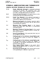
Отзывы: