


Base Unit Manual
2019 Cervis, Inc.
iii
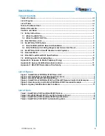
Table of Contents
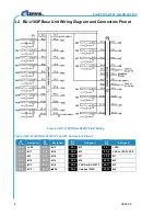
BU-x18XF Base Unit Wiring Diagram and Connectors Pinout ..................................... 6
SmaRT BU-x18XF in SmaRT Remote Control Systems ................................................... 7
List of Figures
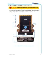
Figure 4. SmaRT BU-x18XF/BU-xH18XF with SmaRT Remote Control Unit Examples .......... 7
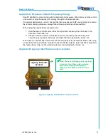
Figure 5. Remote control unit to BU-x18XF/BU-xH18XF Associate Example .......................... 8
List of Table
Содержание SmaRT BU-218XF-EXT
Страница 1: ...2019 Cervis Inc SmaRT BU x18XF and BU xH18XF Base Units User Manual U069 3 3...
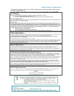
Страница 6: ...SmaRT BU x18XF and BU xH18XF U069 3 3 2 Never use the system if failure is detected...
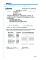
Страница 16: ...SmaRT BU x18XF and BU xH18XF U069 3 3 12 Appendix C BU 2H18XF Declaration of Conformity...


