Cervis SmaRT BU-218XF-EXT Скачать руководство пользователя страница 14


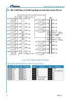
SmaRT BU-x18XF and BU-xH18XF 


U069.3.3 

10 

7.0 

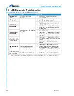
LED Diagnostic Troubleshooting 

Table 4. SmaRT BU-x18XF LED Troubleshooting Hints 

Indication 

Cause 

Solution

† 

Unmarked LED 
active 

Input power polarity is 
reversed. 


Adjust wiring connections to achieve 
correct polarity. 

+V1, +V2, +V3  

Electrical signals not activating 
the LEDs.


Is +VDC input power present?


RTX/RRX (LEDs 2 
& 3) not active 


Check for obstructions preventing line-of-
sight transmission.


Check that the remote control unit is active.


Re-associate the remote control unit with 
the base unit. 

CTX/CRX (LEDs 4 
& 5) not active 


Check CAN wiring.


Check that the remote control unit is active.


Re-associate the remote control unit to the 
base unit. 

In/Out LEDs (LEDs 
6 & 7) not active 


Check that the remote control unit LEDs 
are active when the appropriate buttons are 
pushed.


Check that the startup sequence was 
followed. 

ERR LED (LED 8) 
active 

Over-temperature or over-
current channel indication.


Check the outputs for loose wiring, etc. 


Active channel current consumption less 
than 1A typical. (This is not a problem in 
cases where less than 1A draw is a normal 
condition.) 

Health LED (LED 1) 
blinking rapidly 

Indicates an internal problem.


Contact Cervis, Inc. service department. 

† – If the recommended solutions do not resolve the issue, contact the Cervis, Inc. service department. 


Содержание SmaRT BU-218XF-EXT

Страница 1: ...2019 Cervis Inc SmaRT BU x18XF and BU xH18XF Base Units User Manual U069 3 3...

Страница 2: ...Industry Canada Statement This device complies with Industry Canada licence exempt RSS standard s Operation is subject to the following two conditions 1 this device may not cause interference and 2 th...

Страница 3: ...gnostic Troubleshooting 10 Appendix A Exposure to Radio Frequency Energy 11 Appendix B Agency Identification Label Locations 11 Appendix C BU 218XF Declaration of Conformity 12 List of Figures Figure...

Страница 4: ...lation or troubleshooting at 724 741 9000 Cautions and Notes Cautions warn the user that certain circumstances or conditions warrant that the user be aware of a presence of danger that may result in h...

Страница 5: ...regulations are fully followed Make sure that this manual is permanently available to the operator and maintenance personnel Keep the remote control unit out of reach of unauthorized personnel At the...

Страница 6: ...SmaRT BU x18XF and BU xH18XF U069 3 3 2 Never use the system if failure is detected...

Страница 7: ...lows these units to operate worry free in harsh weather conditions Color keyed or wire numbered weatherproof cable harnesses connect the controlled devices These base units create a robust communicati...

Страница 8: ...EXT AI2 CAN 2 4GHz 100mW External 2 4 20mA IN CAN No No BU 2H18XF INT AI2 CAN 2 4GHz 100mW Internal 2 4 20mA IN CAN No No BU 2H18XF EXT DIS AV2 CAN 2 4GHz 100mW External 2 0 10V IN CAN Yes No BU 2H18X...

Страница 9: ...mounting the base unit and connecting the wiring harnesses use the configuration diagrams supplied by Cervis Inc as a guide Dimensions for drilling mounting holes are shown in Figure 2 Wiring diagram...

Страница 10: ...XF BU xH18XF P1 and P2 Connectors Pinout P1 Pin Assigned P1 Pin Assigned P2 Pin Assigned P2 Pin Assigned P1 1 VDC P1 7 M13 P2 1 M5 P2 7 VDC P1 2 M17 P1 8 M14 P2 2 M6 P2 8 CANL or RS 232 RX P1 3 M9 P1...

Страница 11: ...the SmaRT Console Remote examples shown in Figure 4 Communications between the base unit and the remote control units are established at the factory using the Associate process which can also be easil...

Страница 12: ...sconnect power from the base unit and turn OFF the handheld remote control unit 2 Stand near the base unit in unobstructed clear line of sight with the remote control unit in hand 3 Simultaneously pre...

Страница 13: ...4 CAN TX flashes when active 5 CAN RX flashes when active 6 Output blinks once per second when active 7 Input blinks once per second when active 8 Error solid when active Enclosure Dimensions mm 133...

Страница 14: ...5 not active Check CAN wiring Check that the remote control unit is active Re associate the remote control unit to the base unit In Out LEDs LEDs 6 7 not active Check that the remote control unit LED...

Страница 15: ...ody in the direction of the base unit 2 Keep the remote control unit at least 15mm inch away from the body and only use carrying cases belt clips or holders that are approved by Cervis Inc When active...

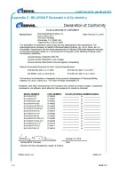
Страница 16: ...SmaRT BU x18XF and BU xH18XF U069 3 3 12 Appendix C BU 2H18XF Declaration of Conformity...

Страница 17: ...Inc 13 Visit our Web site at www cervisinc com Phone 724 741 9000 Fax 724 741 9001 2019 Cervis Inc All rights reserved Content is subject to change without notice Revised manuals are available for do...

Отзывы: