


page 50
www.centsys.com
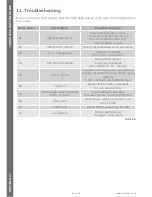
The
SDO4
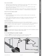
offers seven menu levels pertaining to six different functions that can be
activated either via a handheld remote control or via the four-button wireless wall
switch. Each menu level and function has a different effect upon the controller and
the load which it controls. In addition, a seventh menu can be accessed which will learn
the buttons of a four-button remote control or wall switch in the order described below.
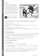
9.1. Entering ‘Learn’ mode
9.1.1. Using the Learn button
Momentarily press the Learn button. The LED Display will display “00”
1
to confirm that
the user is in the programming menu. Scroll using the ‘+’ and ‘-’ buttons to choose
desired function. When desired function is selected, press and hold transmitter button
for approximately 5 seconds. The Courtesy light will stop flashing to indicate a valid RF
signal. The remote is now learned into the system. The number of beeps indicates the
function that has been learned.
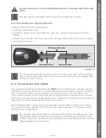
9.1.2. Using a Remote Transmitter.
Only transmitter buttons learned into “Light Function / Remote Learning” can initiate
remote learning. Press and hold transmitter button for approximately 5 seconds.
The courtesy light will flash and the display will show ‘ru’. Scroll using the ‘+’ and ‘-’
buttons to choose the desired function. When the desired function is selected, press and
hold the transmitter button. The Courtesy light will stop flashing to indicate a valid RF
signal. The remote is now learned into the system. The number of beeps indicates the
function that has been learned.
Any button can be set to control the
Trigger, Courtesy light
,
Holiday Lockout,
Autoclose Override, Open Only,
or
Close Only
features.
1. With an empty memory, ‘00’ will be displayed, otherwise it will display the number of remotes learned into the system.
9.2. Operating Functions
9.2.1. Run Function - Open / Stop / Close
This function is associated with opening, stopping and closing the door only.
Operation
Momentarily press the associated remote control button to open, stop or close the door.
If the door is busy closing, pressing the remote control button will cause the door to
stop and a second press will reverse its direction of travel and start opening.
If, on the other hand, the door is busy opening, pressing the remote control button will
cause the door to stop. Pressing the remote control button a second time will cause the
door to reverse its direction of travel and start closing.
Learning procedure
Enter Learn mode, (Refer 9.1). Using the ‘+’ and ‘-’ buttons, select ‘ru’. Press and hold
the transmitter button until the display flashes “ru” and the buzzer beeps once.
The system will remain in this learn mode for 10 seconds after the last
remote or wall transmitter button has been learned and automatically exit after
this time. A function can be learned to any button, provided that the button has
not yet been learned to another function.
9. Programming remote controls
S
ECTION
9
PROGRAMMING
REMOTE
CONTROLS
Содержание SD04
Страница 61: ...page 61 www centsys com Notes NOTES...
Страница 62: ...page 62 www centsys com Notes NOTES...
Страница 63: ...page 63 www centsys com Notes NOTES...


