Page 8
SKU 96087
for technical questions, please call 1-800-444-3353.
OPERAtIng InStRuCtIOnS
note: Prior to starting the Compressor, read and familiarize yourself with the to
Stop the Compressor procedures listed below.
to Start the Compressor:
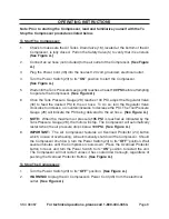
Check to make sure the Air Tank’s Drain Valve (18), located at the bottom of the Air
Compressor, is fully closed. Pull on the Safety Valve (5) to verify that it is unstuck.
(See figure A.)
Connect an air hose (not included) to the air outlet of the Compressor.
(See figure
A.)
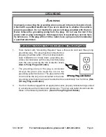
Plug the Power Cord (35) into the nearest 120 volt, grounded, electrical outlet.
Turn the Power Switch (23) to its
“On”
position to start the Compressor.
(See figure A.)
Wait until the Tank Pressure Gauge (28) reaches at least
100 PSI
before attempting
to operate the Compressor.
(See figure A.)
Once the Tank Pressure Gauge (28) reaches 100 PSI, adjust the Regulator Valve
(30) to feed the desired PSI to the air hose. To do so, turn the Regulator Valve
clockwise to increase, or counterclockwise to decrease the PSI. The Tool Pressure
Gauge (28) will indicate the PSI being delivered to the air hose.
(See figure A.)
nOtE:
When the maximum air pressure,
135 PSI
is reached as indicated by the
Tank Pressure Gauge (28), the motor will stop. The Compressor will automatically
restart when the air pressure drops below
100 PSI
.
(See figure A.)
IMPORtAnt:
The Air Compressor features an Overload Protector (24) button
which, in case of overheating, will automatically shut down the Compressor. Should
the Compressor shut down, turn the Power Switch (23) to its
“Off”
position. Wait
several minutes until the Compressor cools down. Press the Overload Protector
button to reset, and turn the Power Switch to its
“On”
position to restart the unit.
The Compressor will not restart unless it has cooled down enough, regardless of
pushing the Overload Protector Button.
(See figure A.)
to Stop the Compressor:
Turn the Power Switch (23) to its
“Off”
position.
(See figure A.)
WARnIng!
Unplug the Air Compressor’s Power Cord (35) from the electrical
outlet.
(See figure A.)
1.
2.
3.
4.
5.
6.
7.
8.
1.
2.


