background image

Page 7

SKU 44991

2.

Adjust the position of the Limit Block (65) up or down. Refer to the Ruler (67) on the

side of the Vertical Support (68).

3.

Tighten the Handle.

Adjusting the Vertical Support Angle

1.

Using the Large Wrench (accessory A),

loosen Lock Nut (70) only enough to allow
movement of the Vertical Support (68).

Caution: Avoid injury or damaging machine, hold
the Vertical Support in place to keep it from fall-
ing to the left or right during adjustment.

2.

Adjust the Vertical Support angle as needed (45 degrees left or right, maximum).

Check Ruler (44) for angle.

3.

When the Vertical Support is at the desired angle, tighten Lock Nut (70) again.

Basic Drilling and Milling Procedure

During the following procedure, it may be helpful to refer to the machine photo on page 5.

1.

Make desired changes and adjustments to the machine for drilling or milling.

2.

Set an appropriate speed for drilling or milling the workpiece.

Use the Speed Control Knob (134) to adjust the Spindle speed. For cutting metal, the

speed range should be between 200 to 2500 RPM. Faster speeds are generally used
when milling softer materials and drilling small holes; And slower speeds for milling
harder material and drilling larger holes.

3.

Using a fixture (not supplied) mount the workpiece to the Working Table (19).

4.

Adjust the Limit Block (65) height.

This will enable Spindle movement to the desired cut, and disable an over cut which

could damage the workpiece fixture or Work Table.

5.

Adjust the Working Table Longitudinal Feed Hand Wheel (X-Axis) and the Cross Feed

(Y-Axis) Hand Wheel (5) into position for milling or drilling.

One step turn of the Hand Wheel moves the Work Table 0.03 mm; one complete turn

moves it 1.5 mm.

6.

Remove any tools or obstacles from in and around the Work Table.

7.

Turn the machine on. Lift the Emergency Stop Switch (137) cover, and pull button out.

8.

If necessary, adjust the Spindle speed with the Speed Control Knob (134).

9.

Begin milling or drilling.

Use the Operating Lever (58) to make large adjustments to the Spindle height. For fine

adjustments, use the Fine Feeding Wheel (93).

Refer to the ruler on the Vertical

Support to determine drilling or milling depth.  Caution: Keep hands and fingers clear
of the working table and workpiece while the machine is in operation.

(68)

(70)

Содержание 44991

Страница 1: ...ND OPERATING INSTRUCTIONS 3491 Mission Oaks Blvd Camarillo CA 93011 Visit our Web site at http www harborfreight com Copyright 2000 by Harbor Freight Tools All rights reserved No portion of this manual or any artwork contained herein may be reproduced in any shape or form without the express written consent of Harbor Freight Tools For technical questions and replacement parts please call 1 800 444...

Страница 2: ...e and dry place for future reference Safety Warnings and Precautions WARNING When using tool basic safety precautions should always be followed to reduce the risk of personal injury and damage to equipment Read all instructions before using this tool 1 Keep work area clean Cluttered areas invite injuries 2 Observe work area conditions Do not use machines or power tools in damp or wet locations Don...

Страница 3: ...eck that keys and adjusting wrenches are removed from the tool or machine work surface before plugging it in 13 Avoid unintentional starting Be sure the switch is in the Off position when not in use and before plugging in 14 Stay alert Watch what you are doing use common sense Do not operate any tool when you are tired 15 Check for damaged parts Before using any tool any part that appears damaged ...

Страница 4: ...conditions and situations that may occur It must be under stood by the operator that common sense and caution are factors which cannot be built into this product but must be supplied by the operator Unpacking When unpacking check to make sure the following parts and accessories are included ITEM DESCRIPTION A Large Wrench B 13 mm Drill Chuck with Taper Shank C Oil Bottle D Fixing Pin E L Hex Wrenc...

Страница 5: ...of the Chuck lightly with a piece of wood to securely set the Chuck 2 If necessary screw the Handles into the Small Hand Wheels 3 Check the angle of the Vertical Support 68 for true vertical Check all bolts for tightness Operation This Mini Milling Drilling Machine is capable of machining metal and nonmetallic stock by cutting drilling and milling It can cut circular surfaces both inside and out c...

Страница 6: ... and machinery 5 Insert the Fixing Pin accessory D on the right side of the Spindle sleeve Refer to page 4 6 Using the 14 open end wrench accessory G tighten clockwise the Spindle draw bar A to lock in the Taper Shank Cutter into the Spindle 7 Pull out the Fixing Pin and replace the Protective Cover Removal of the Taper Shank Cutter 1 Pull off the Protective Cover 126 2 Insert the Fixing Pin acces...

Страница 7: ...2500 RPM Faster speeds are generally used when milling softer materials and drilling small holes And slower speeds for milling harder material and drilling larger holes 3 Using a fixture not supplied mount the workpiece to the Working Table 19 4 Adjust the Limit Block 65 height This will enable Spindle movement to the desired cut and disable an over cut which could damage the workpiece fixture or ...

Страница 8: ...olts and handles for tightness 4 Store cutting tools in a wooden box or other moisture proof package 5 Cover the machine when not in use 6 Sharpen cutting tools as soon as they become dull 7 Always keep the taper shank clean 8 Store all tools and accessories in a clean and dry location near the machine 9 Always use the supplied tools and wrenches to make repairs and adjustments PLEASE READ THE FOL...

Страница 9: ...Page 9 SKU 44991 Parts List NOTE Some parts are listed and shown for illustration purposes only and are not available individually as replacement parts 4 REV 03 05 ...

Страница 10: ...Page 10 SKU 44991 with REV 11 02 ...

Страница 11: ...Page 11 SKU 44991 Longitudinal Y Axis and Cross X Axis Assembly Drawing ...

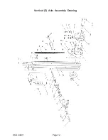
Страница 12: ...Page 12 SKU 44991 Vertical Z Axis Assembly Drawing ...

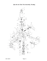
Страница 13: ...Page 13 SKU 44991 Spindle and Gear Box Assembly Drawing ...

Отзывы: