


DRSplus
–
Operating Manual
11/58
4.
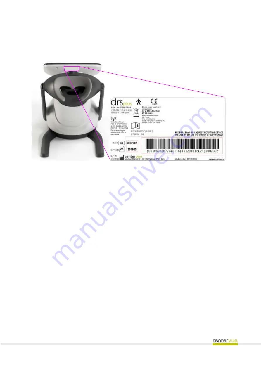
Labels
The device label is located on the back side of the display, as shown in Fig. 10
Fig. 10
–
Device label
DRSplus
–
Operating Manual
11/58
4.
Labels
The device label is located on the back side of the display, as shown in Fig. 10
Fig. 10
–
Device label


