


CENTENT CN0165 MICROSTEP DRIVE
4
POWER SUPPLY INPUTS
Terminal 2 connects to the positive output from the power supply. The voltage range is
+18 to +80 VDC. The power supply may be unregulated. Limit the ripple voltage
(unregulated supplies) to a maximum of 10% of the DC output voltage. Terminal 1 is
the ground connection. Do not use Terminal 12 for power supply ground; it is the return
connection for the Current Set resistor.
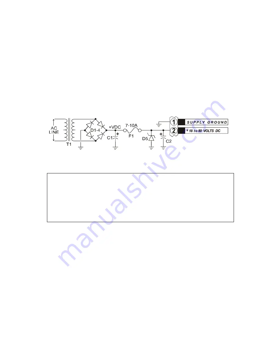
For those users that wish to build their own power supply,
X
Figure 3
X
shows a suggested
circuit. Because of the electrical noise generated by these drives, it is not recommended
that the supply be shared with low level logic circuitry.
Figure 3 - Power Supply
The power supply terminals should have a capacitor of 470µf or greater
connected across them. This is particularly important for regulated power
supplies since they usually have little output capacitance. Locate the
capacitor as close to Terminals 1 & 2 of the CN0165 as possible (see
X
Figure 3
X
, C2). Be sure the voltage rating for the capacitor is higher than
the drive’s supply voltage.
During rapid deceleration of large inertial loads from high speeds, step motors become
generators of considerable electrical power. This is returned to the power supply by the
step motor drive. If the supply cannot absorb this power, the voltage generated may
exceed the 80 volt limit of the CN0165, thus damaging the drive and power supply.
To protect the drive and power supply, the user may connect an external zener diode
from Terminal 2 to ground (see
X
Figure 3
X
, D5). This diode will protect the drive from
over-voltage conditions. Recommended diodes are 1N4762 (one watt) or 1N5375 (five
watt). Note the 7-10 amp fuse (F1) placed in series with Terminal 2 and the power
supply. Be sure this fuse is located between the power supply and the zener diode. In
case of an over-voltage condition, the zener diode and fuse may be destroyed, but the
CN0165 and the power supply will be protected from damage.
The power supply current required depends on the motor being used and whether the
configuration is for parallel or series operation. See Motor Winding Configuration in
the Performance section of this manual on page
X
19
X
for a complete explanation of motor
wiring options.
Содержание CN0165
Страница 4: ......