


42
The drainage tube should also be routed through the wall. All these
connections should be properly selected, connected, routed and
secured.
CONNECTING COPPER TUBES
–
Use special tubes designed for refrigeration equipment. Do not use
contaminated tubes (with moisture and dust).
–
Tubes should be connected by soldering.
–
The standard pipeline length is 5 m. If the distance between the units
exceeds 5 m, tubes of a larger diameter should be used. Data on
tube diameter and length is provided in Table 1. Do not exceed the
specified limits, otherwise compressor malfunctions are likely to
occur. Try to install the pipeline with as few bends as possible and
following the shortest route possible, as the increased length and
number of bends reduces the efficiency of the air conditioner and
increases power consumption.
–
Cut length of tube with a tube cutter and debur the edges with a
special tool, spreading and straightening the edge. Do not use an
ordinary saw and file for removing burrs, this will inevitably leave
sawdust inside the tubes and cause damage to the compressor
within a short time.
–
Do not bend one and the same section of tube more than 3 times (this
may lead to micro-cracking). Use a pipe bender to bend the tubes.
–
Pull thermal insulation sleeves over the prepared lengths of tube.
The insulation should be continuous along the whole pipeline,
including inside the wall. Seal the joints between the length of the
insulating sleeve with adhesive metal-coated foil ensure a very
tight fit of the edges. The quality of heat insulation is important, as
the condensate forming un-insulated tube sections may penetrate
inside the wall, causing stains and damage.
–
Pass the copper tubes with the insulation installed through the
opening in the wall. Before doing that seal the end of the tube by all
means to prevent dust from getting inside the tube (it is advisable
to plug the tubes on both ends immediately after cutting and leave
them sealed until connection). This is very important as dust can
damage the compressor very quickly.
ELECTRIC CABLE CONNECTION
–
The outdoor and indoor units are equipped with removable cover
plates underneath which cable connection terminals are located.
–
Strip the cable end of insulation and install a lug on the bare
core, compressing it with tongs. Connect the thus prepared cable
according to the diagram (see Fig. 7 of the Appendix).
DRAINAGE TUBE
–
Connect the drainage tube to the relevant outlet on the indoor unit
and route it through the wall. Choose the length of the tube so that
its end is located 60 to 80 cm away from the wall. The drainage tube
should be routed with a minimum gradient of 1cm per 1m towards
the free end.
–
The tube should be secured every 1m to avoid sagging. Otherwise
the accumulated condensate can be discharged back into the room.
It is advisable to plug the end of the tube when pulling it through
the wall opening.
HEAT INSULATION AND SEALING
Carefully wrap the copper tubes, electric cable and drainage tube
together into a single bundle with the metallic adhesive tape, trying
not to damage the pipeline and drainage tube (see Fig. 9 of the
Appendix).
The wrapping should start from the lower part of the outdoor unit and
move towards the indoor unit.
If the indoor unit is located lower than the outdoor unit, route the
drainage tube separately from the other pipelines to prevent the back
flow of condensate.
Fasten the tube bundle to the wall in several places. If desired, all
tubes can be concealed inside a wall — cut a groove into the wall, lay
the tubes in the groove and close it with mortar after the functionality
tests. The pipelines should be installed at a gradient of 20:1 towards
the outdoor unit.
To avoid the ingress of rain water or foreign objects into the room or
the system, the opening in the wall should be sealed with putty, resin
or sealing compound after installing the pipelines and cables.
If the outdoor unit is located higher than the indoor unit the pipeline
should be bent so that its lowest point is located below the wall
opening. This will prevent the flow of rain water into the room or
system along the tube (see Fig. 10 of the Appendix).
CONNECTIONS BETWEEN THE UNITS
If the elevation difference between the units is less than 5meters,
make a loop for oil retention (oil trap) at the lowest point of the gas
pipeline.
If the elevation difference between the units exceeds 5meters, then a
loop for oil retention (oil trap) should be made every 5 meters in the
lowest section of the tube and a short loop (liquid trap) made at the
highest point of the pipeline (see Fig. 11 of the Appendix).
If the outdoor and indoor units are installed on the same level and the
pipeline length is less than 10 meters, no oil retention and liquid trap
loops will be necessary.
If the outdoor and indoor units are installed on the same level and the
pipeline length exceeds 10 meters, then an oil retention loop (oil trap)
should be made every 10 meters.
TUBE CONNECTIONS
Connect the tube to the indoor unit first. Unscrew the nuts from the
indoor unit ports. The hissing of escaping gas will be heard as the nuts
are loosened. This is nitrogen vented out. This is normal: the system is
filled with nitrogen at the factory to prevent internal oxidation. When
the hissing stops pull off the sealing caps, remove the nut, set it on the
tube, after which the tubes can be flared.
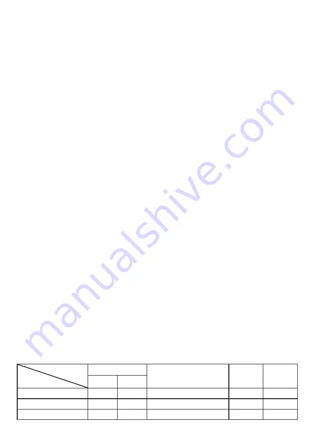
Table 1
Parameters
Model
Tube diameter (mm)
Max. pipeline length (m)
Height
(m)
Max.
number of
bends
Liquid
Gas
СТ-66Р60
9.52
19
50
30
10
СТ-66Р48
9.52
19
50
30
10
СТ-66Р36
9.52
19
30
20
10
Содержание air CT-66P36
Страница 10: ...9 Рис 6 Рис 1 Рис 2 Рис 3 Рис 4 Рис 5 Рис 7 Рис 8 A 300 мм B 1500 мм C 300 мм D 500 мм ПРИЛОЖЕНИЕ ...
Страница 45: ...44 Fig 2 APPENDIX Fig 3 FRONT VIEW Fig 4 Fig 5 SIDE VIEW Tilt towards the back wall 1 2 100 Fig 1 Floor ...
Страница 57: ...56 ...
Страница 58: ...57 ...
Страница 59: ...58 ...
Страница 60: ...59 59 ...