


12
14. Press and hold the
MODE
button to return to current
measurement.
15. Press EXIT for 2 seconds into the function of AC+DC. Test DC
and AC TURE Rms.
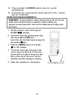
RESISTANCE MEASUREMENTS
WARNING:
To avoid electric shock, disconnect power to the unit
under test and discharge all capacitors before taking any
resistance measurements. Remove the batteries and unplug the
line cords.
1. Set the function switch to the green
Ω
CAP
position.
2. Insert the black test lead banana plug
into the negative
COM
jack.
Insert the red test lead banana plug into
the positive
jack.
3. Press the
MODE
button to indicate
―
”
on the display.
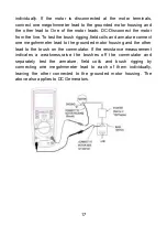
4. Touch the test probe tips across the
circuit or part under test. It is best to
disconnect one side of the part under
test so the rest of the circuit will not
interfere with the resistance reading.
5. Read the resistance in the display.
Содержание DT-9985
Страница 1: ...User s Guide True RMS Industrial Multimeter...
Страница 2: ...1...
Страница 32: ...31...


