50
CHL-350 TECHNICAL MANUAL
03-2021
Translation of the original manual
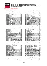
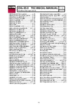
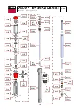
25. LIST OF COMPONENTS.
2020 Swift connector air gun
...................
p.31
2061 M6 Grease nipple
...............................
p.20
2062 Grease nipple cover
.........................
p.20
2100-A Liquid filter set
....................
p.9, 16, 24
2102 Watertight washer 1”
........................
p.17
2103 O-ring Øint30 x 2
..............................
p.24
2104 Filter body
...........................................
p.24
2105 Filter holder
.........................................
p.24
2106 Filter
......................................................
p.24
2107 Safety ring Ø20 x 1.2
........................
p.24
2108 Watertight washer 3/4”
....................
p.24
2109 M-M 3/4”G - 1 1/16”SAE joint
.........
p.24
2111 Plug 3/8”
........................................
p.17, 24
2112 Watertight washer 3/8”
..............
p.17, 24
2113 M-Htl 3/4”Gas joint
............................
p.24
2114 Watertight washer 1/2”
....................
p.27
2208 SPARE KIT filter unit
........................
p.24
2213 SPARE KIT Piston seal
....................
p.23
2332 Air distributor set
.......................
p.11, 25
2421 O-ring Øint14 x 2,5
...........................
p.18
2701 ISO line
.................................................
p.29
2702 POLY line
.............................................
p.29
2703 ISO hose
..............................................
p.31
2704 POLY hose
..........................................
p.31
2707 Hose wire
......................................
p.29, 31
2708 Hose air conduit (tube Ø6)
.......
p.29, 31
2750 Anterior connecting block
..............
p.29
2751 Insulator separator
...........................
p.30
2752 End connecting block
......................
p.31
2758 Thermostat
..........................................
p.26
2850 Sphere Ø18
.........................................
p.17
2910 Poly heater inlet hydraulic pipe
......
p28
2911 Poly heater outlet hydraulic pipe
..
p.28
2912 Iso heater inlet hydraulic pipe
.......
p.28
2913 Iso heater outlet hydraulic pipe
.....
p.28
2914 Air hose
................................................
p.28
2915 Air pressure gauge hose
.................
p.28
2916 ISO gun line (hydraulic)
...................
p.31
2917 POLY gun line (hydraulic)
...............
p.31
3002 Manhole cover
....................................
p.14
3004 ISO hose fitting
..................................
p.30
3005 POLY hose fitting
..............................
p.30
3007 Electrical connectors
.......................
p.29
3017 Polyol heater cover
.............................
p.9
3018 Isocyanate heater cover
..............
p.9, 26
3053 Ø14 Spring for resistance
...............
p.26
3056 Thermocouple probe
........................
p.26
3057 Probe fitting
........................................
p.26
3073 Isocyanate heater
..............................
p.26
3074 Ø14x485 1500W resistance
.............
p.26
3075 Polyol heater
.......................................
p.26
3076 Tapón 3/4” NPT
..................................
p.26
3100-C Armaflex thermal coating
...........
p.31
3500 Bicolor anti-abrasion covering
......
p.31
3503 Motor ventilation grill
.........................
p.9
3530 Front housing
.......................................
p.9
3531 Isocyanate heater protection
.........
p.12
3532 Polyol heater protection
..................
p.13
3533 Transformer housing
..........................
p.9
3534 Back cover
....................................
p.11, 12
3535 Control cabinet
..................................
p.12
3536 Control cabinet cover
.........................
p.9
3538 Transformer cover
...............................
p.9
3539 Hex. pillar for protection
...........
p.20, 21
3540 Piston
....................................................
p.23
3541-A Piston rod (isocyanate side)
......
p.23
3541-B Piston rod (poliol side)
................
p.23
3542 Bronze guide bushing
...............
p.20, 21
3545 Cylinder body
.....................................
p.19
3546 Piston rod
............................................
p.22
3547 Guide and Buffer seal housing
......
p.22
3548 Piston Head Cap
................................
p.22
3549 Piston Head
.........................................
p.22
3550 Pump head
..........................................
p.17
3551-A Base (Iso side)
...............................
p.21
3551-B Base (Polyol side)
.........................
p.20
3552 Closing ring
..................................
p.20, 21
3553 Inlet ball seat
......................................
p.17
3554 Ball stopper
.........................................
p.17
3555 Lubrication cylinder
.........................
p.21
3556 Hexagonal pillar
..........................
p.20, 21
3559 Piston rod union
................................
p.22
3561 M12 tie rod
...........................................
p.19
3565 Anti-turn guide
...................................
p.20
3568 Spring
...................................................
p.17
3569 Plastic plug 1/4”NPT
..................
p.15, 21
3570 Solenoid valve base plate
...............
p.18
3571 Hose outlet unit
....................................
p.9
3572 Input non-return valve
......................
p.15
3573 Outlet DOP check valve
.............
p.15,28
3575 Reduction M-M 3/4”G–3/8”G
....
p.27, 28
3576 Tee F-M-M 3/8”G
................................
p.28
3577 Reduction F3/8”G – M1/4”G
...........
p.28
3578 Elbow M3/8”NPT – pipeØ12
.............
p17
3579 Air distributor
.....................................
p.25
3582 Cylinder head (Iso side)
...................
p.21
3583 Cylinder head (Polyol side)
............
p.20
3584 Piston rod union lubrication side
.
p.22
3585 Piston rod union end of stroke side
(mechanical; optional)
...............................
p.22
3586 Piston rod union end of stroke side
(magnetic)
......................................................
p.22
3591 Bost pump sleeve 3/8”
.....................
p.28
3592 Return tank sleeve 1/2”
...................
p.28
3593 Hidraulic pr. gage sleeve 1/4”
.
p.27, 28
3595 Recirculation sleeve 3/8”
................
p.27
3597 Suction pump set 1”
.........................
p.27
3598 Ball valve 1”
........................................
p.27
Содержание CHL-350
Страница 1: ...CHL 350 HYDRAULIC SYSTEM FOR SPRAYING POLYURETHANE POLYUREAS AND BI COMPONENTS TECHNICAL MANUAL 2021 ...
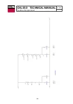
Страница 33: ...33 CHL 350 TECHNICAL MANUAL 03 2021 Translation of the original manual 14 ELECTRICAL DIAGRAMS ...
Страница 34: ...34 CHL 350 TECHNICAL MANUAL 03 2021 Translation of the original manual ...
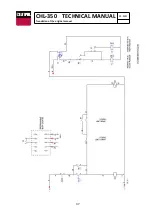
Страница 35: ...35 CHL 350 TECHNICAL MANUAL 03 2021 Translation of the original manual ...
Страница 36: ...36 CHL 350 TECHNICAL MANUAL 03 2021 Translation of the original manual ...
Страница 37: ...37 CHL 350 TECHNICAL MANUAL 03 2021 Translation of the original manual ...
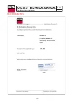
Страница 60: ...60 CHL 350 TECHNICAL MANUAL 03 2021 Translation of the original manual 28 CE DECLARATION ...
Страница 61: ...61 CHL 350 TECHNICAL MANUAL 03 2021 Translation of the original manual ...

