Table 1. Setting of SW2 microswitch for 1-x version
Function
SW2-1
DTR-DSR
SW2-2
RTS-CTS
SW2-3
DTR
SW2-4
DSR
SW2-5
RTS
SW2-6
CTS
Tx, Rx signals conversion (default setting)
OFF
OFF
OFF
OFF
OFF
OFF
Tx, Rx signals conversion, RTS looped with CTS and DTR with DSR
ON
ON
OFF
OFF
OFF
OFF
Table 2. Setting of SW2 microswitch for 2-x version
Function
SW2-1
DTR-DSR
SW2-2
RTS-CTS
SW2-3
DTR
SW2-4
DSR
SW2-5
RTS
SW2-6
CTS
Tx, Rx signals conversion (default setting)
OFF
OFF
OFF
OFF
OFF
OFF
Tx, Rx, RTS, CTS signals conversion
OFF
OFF
OFF
OFF
ON
ON
Tx, Rx, DTR, DSR signals conversion
OFF
OFF
ON
ON
OFF
OFF
Tx, Rx, RTS, CTS signals conversion, DTR looped with DSR
ON
OFF
OFF
OFF
ON
ON
Tx, Rx, DTR, DSR signals conversion, RTS looped with CTS
OFF
ON
ON
ON
OFF
OFF
Tx, Rx signals conversion, RTS looped with CTS and DTR with DSR
ON
ON
OFF
OFF
OFF
OFF
3.2. CONFIGURATION OF POLARIZATION AND LINE TERMINATION RS-485 BUS
The SW1 microswitch is used for enabling the polarization MASTER type (terminals Tx+/DATA+/(A), Tx-/DATA-/(B)) of RS485 bus and
connection of RS-485/RS-422 terminating resistors. The table below show manufacturer's configuration settings.
The 6-position microswitch SW1 is located on one side of the converter.
ATTENTION !!!
ENABLING/DISABLING THE POLARIZATION OF MASTER TYPE RS485 BUS, FOLLOWS AFTER ENABLING/DISABLING BOTH
SECTION OF SW1-4 & SW1-5 MICROSWITCH.
Table 3. SW1 microswitch setting
Position
Function
Default
Setting
SW1-1
ON - enable RS422 mode | disable RS485 mode,
OFF - disable RS422 mode | enable RS485 mode,
OFF
SW1-2
NC – not connected
---
SW1-3
ON - connection of Line Termination (terminator) 120Ω to terminals Rx+, Rx-
OFF - disconnection of Line Termination (terminator) 120Ω to terminals Rx+, Rx-
OFF
SW1-4
ON – enable polarization of MASTER type RS485 bus, to terminal Tx-/DATA-/(B),
OFF - enable polarization of SLAVE type RS485 bus, to terminal Tx-/DATA-/(B),
OFF
SW1-5
ON – enable polarization of MASTER type RS485 bus, to terminal Tx+/DATA+/(A),
OFF - enable polarization of SLAVE type RS485 bus, to terminal Tx+/DATA+/(A),
OFF
SW1-6
ON - connection of Line Termination 120Ω to terminals Tx+/DATA+/(A), Tx-/DATA-/(B).
OFF - disconnection of Line Termination 120Ω to terminals Tx+/DATA+/(A), Tx-/DATA-/(B).
OFF
4. INSTALLATION
This chapter will show how to connect ADA-I91402 to RS-485/RS-422 bus.
The GND and 100R terminals are used for connection of RS485/RS422 interface grounds, to compensate the ground potential of
devices operating on RS485/RS422 bus. This connection should be done individually for each systems if standard wiring of
RS485/RS422 bus not provide correct transmission.
To reduce disturbance from environment, it is recommended to:
– use multipair type shielded cables, which shield can be connected to the earthing on one end of the cable,
– lay signal cables at a distance of not less than 25 cm away from power cables,
4.1. CONNECTION TO RS485/RS422 BUS
RS485/RS422 interface of ADA-I91402 converter is available on screw terminal block described as: Tx+/DATA+, Tx-/DATA-, Rx+, Rx-,
RTS+/DTR+, RTS-/DTR-.
ADA-I91402 can operate on RS422 bus or RS485 bus - both buses need suitable wiring.
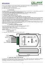
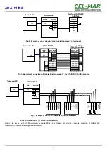
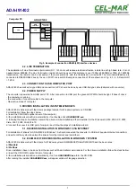
4.1.1. CONNECTION TO RS422 OR RS485 (4-WIRE) BUS
Examples of connection ADA-I91402 to RS422 4-wire bus or RS485(4W) in point-to-point and multi-point topology are shown below.
5
ADA-I91402
Содержание ADA-I91402
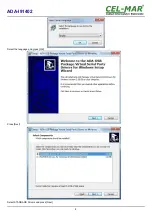
Страница 8: ...Select the language and press OK Press Next Select STANDARD Drivers and press Next 8 ADA I91402...
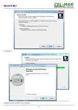
Страница 9: ...Press Install Press Next will be installed Drivers for USB Bus 9 ADA I91402...
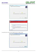
Страница 10: ...Press Install this driver software anyway Installation of drivers for USB bus will start 10 ADA I91402...


