background image

16

13

These points must be checked after
pump installation and before starting up
the pump.

1) Read the instruction manual 

thoroughly and understand it.

2) Review the pump order headsheet

for the service rating of the pump
and any special features.

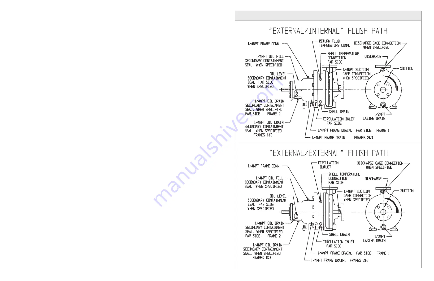
3) Check all piping connections making

certain they are both tight and in the
proper places. Piping includes flush-
ing, cooling or heating piping.
Be sure that the casing drain and
the containment shell drain are not
connected together.

4) Make certain no insulation has been

placed over any air cooling surfaces
of the pump or its auxiliary piping.

5) Make sure the baseplate has been

properly installed.

6) Check the electrical or steam line

connections to the driver.

7) If the pump is equipped with air

cooled (finned) auxiliary piping,
make sure the drive motor is fan
cooled.

8) Break the coupling by removing

the coupling spacer and bump the
motor starting button to check
motor rotation. Operating the
pump in reverse rotation may
cause extensive damage.

If the driver rotation is incorrect,
reconnect the wiring for proper
rotation and re-check.

9) Check the coupling for proper

alignment of the motor and rotor
shafts. Re-align if necessary.
Replace the coupling spacer.

10) If the pump has the optional

“Secondary Containment Seal”
check to see that it is properly
lubricated.

11) Make sure the pump is filled with 

liquid and vented to remove any air.

12) Turn on any cooling or heating to the

pump and/or auxiliary equipment.

13) Rotate the pump shaft by hand to

be sure there is no binding or rub-
bing within the pump or driver.
Correct any difficulties at once.

14) Remove all dirt, waste, tools and

construction debris from the area.

15) Make sure the coupling guard is

securely in place.

16) Start the pump and immediately

check for proper flow and pressure.

17) Perform extra venting procedure if

required. See “Starting the Pump”.

PUMP START-UP CHECKLIST

PIPING CONNECTIONS FOR M300 SERIES PUMPS - EXTERNAL

Содержание Dean Pump M300

Страница 1: ...ng equipment Safety glass es with side shields heavy work gloves use insulated work gloves when handling hot items steel toed shoes hard hat and any other protective gear as needed for protection One example of other gear would be breathing apparatus when working near toxic materials Use only top quality tools Stop the pump Turn off the power supply electricity steam etc to the pump driver motor t...

Страница 2: ...al 13 Optional Protection Systems 14 Temperature Probe 14 Electrical Power 14 Vibration 14 Pressure Switch 14 Level Switch 14 Secondary Containment Seal 14 Pump Lubrication 14 Starting the Pump 15 Pump Start Up Checklist 16 Spare Parts 17 Ordering Spare Parts 17 Secondary Containment Seal Section 17 Pump Section View 18 Parts List 18 Internal Circulation Flow Path 19 Disassembly and Assembly Proce...

Страница 3: ...Watches spring driven or electronic will be ruined if exposed to the strong magnetic field of this pump or its parts WARNING FREIGHT When shipping raw or bare magnet assemblies especially by air special precautions may be necessary Usually the shipment of an assembled pump is not a problem Consultation with Dean Pump and the freight company is recommended This pump is designed incorporating a rela...

Страница 4: ...graph g from the inside of the outer magnet assembly 167 Clean both the outer magnet assembly 167 and the containment shell 150 of any particles which might have been attracted to them to prevent damage to the magnets during operation Ferrous particles which stick to the magnet surfaces can be removed by using a piece of masking tape rubbed sticky side across the magnet surfaces u CAUTION Strong m...

Страница 5: ...ing this operation to protect the magnets f If the pump is equipped with an optional Secondary Containment Seal install new gland O rings 324 325 into the groves in the gland 13 and lubricate the O rings with a light oil Carefully remove both O rings from a new mechanical seal assembly 95 lubricate them with the special lubricant supplied and then re install them into the mechanical seal assembly ...

Страница 6: ...ight be attracted by the magnetic field Any such material is difficult to remove u Remove the four cap screws 180A which retain the bearing cartridge 180 to the casing cover 22 Slide the bearing cartridge 180 from the casing cover 22 The flange of the bearing cartridge 180 is tapped to accept two jackscrews to facilitate disassembly if necessary v Remove the casing cover ring assembly 195 by pryin...

Страница 7: ...um value shown in the chart the inner magnet assembly 175 the outer mag net assembly 167 or both need to be replaced Return these to Dean Pump for determination of which or both are bad To further dismantle the pump perform the following steps in the sequence shown a Insert a piece of flat steel into the periphery of the impeller 3 between the blades of the impeller 3 to restrain it from turning w...

Страница 8: ...scraper Wet the gasket before and during the scraping operation to reduce the possibility of fibers becoming airborne Wear a respirator during this operation and until all debris has been disposed of in a plastic bag Remove all of the gasket material down to clean metal surfaces on both parts that contacted the gasket Place all of the gasket residue in a plastic bag seal the bag and dispose m Remo...

Страница 9: ...on and the possibilities of the release of fluid vapors and or fumes d Remove the coupling guard Remove the coupling spacer e Drain all the fluids from all the auxiliary sub systems lubrication cooling heating etc that are connected to the pump Drain each fluid into a separate container Use caution required for each fluid after reading the MSDS Material Safety Data Sheet for each DISASSEMBLY AND A...

Страница 10: ... outside diameter of the stationary coupling hub Rotate the shaft on which the dial indicator is mounted allowing the indicator button to ride on the outside diameter of the stationary hub The indicator dial movement will show the difference in the center locations of the two shafts Good practice suggests alignment to within 0 002 T I R Angular and offset alignment is adjusted by placing thin meta...

Страница 11: ...54 488 554 433 1202 391 260 645 123 391 454 391 Pump Size Frame I Frame II Frame III ALLOWABLE PIPING LOADS M300 SERIES PUMPS NOTES 1 All forces and moments are considered at through and about the three axes x y and z a All forces Fx Fy Fz F and moments Mx My Mz M listed under the Pump section of the chart are considered at the intersection of the three axes and apply to the pump as a complete uni...

Страница 12: ...ur Dean representative who will assist you in selecting your spares stock ORDERING SPARE PARTS Spare part orders will be handled with a minimum delay if the following information is furnished by the customer with the order 1 Give the pump serial number and size These may be found on the pump nameplate The serial number is also stamped on the suction flange 2 Give the part name part number and mate...

Страница 13: ...acer and bump the motor starting button to check motor rotation Operating the pump in reverse rotation may cause extensive damage If the driver rotation is incorrect reconnect the wiring for proper rotation and re check 9 Check the coupling for proper alignment of the motor and rotor shafts Re align if necessary Replace the coupling spacer 10 If the pump has the optional Secondary Containment Seal...

Страница 14: ...erating watch the pump carefully for overheating vibration and other abnormal conditions If trouble develops stop pump at once and correct the problem CAUTION When the pump is started immediately observe the discharge pressure gauge and or the flow meter to confirm that the pump is actually operating and at the expected values of pressure and flow Operation of a magnetically coupled pump cannot be...

Страница 15: ...erating watch the pump carefully for overheating vibration and other abnormal conditions If trouble develops stop pump at once and correct the problem CAUTION When the pump is started immediately observe the discharge pressure gauge and or the flow meter to confirm that the pump is actually operating and at the expected values of pressure and flow Operation of a magnetically coupled pump cannot be...

Страница 16: ...acer and bump the motor starting button to check motor rotation Operating the pump in reverse rotation may cause extensive damage If the driver rotation is incorrect reconnect the wiring for proper rotation and re check 9 Check the coupling for proper alignment of the motor and rotor shafts Re align if necessary Replace the coupling spacer 10 If the pump has the optional Secondary Containment Seal...

Страница 17: ...ur Dean representative who will assist you in selecting your spares stock ORDERING SPARE PARTS Spare part orders will be handled with a minimum delay if the following information is furnished by the customer with the order 1 Give the pump serial number and size These may be found on the pump nameplate The serial number is also stamped on the suction flange 2 Give the part name part number and mate...

Страница 18: ...54 488 554 433 1202 391 260 645 123 391 454 391 Pump Size Frame I Frame II Frame III ALLOWABLE PIPING LOADS M300 SERIES PUMPS NOTES 1 All forces and moments are considered at through and about the three axes x y and z a All forces Fx Fy Fz F and moments Mx My Mz M listed under the Pump section of the chart are considered at the intersection of the three axes and apply to the pump as a complete uni...

Страница 19: ... outside diameter of the stationary coupling hub Rotate the shaft on which the dial indicator is mounted allowing the indicator button to ride on the outside diameter of the stationary hub The indicator dial movement will show the difference in the center locations of the two shafts Good practice suggests alignment to within 0 002 T I R Angular and offset alignment is adjusted by placing thin meta...

Страница 20: ...on and the possibilities of the release of fluid vapors and or fumes d Remove the coupling guard Remove the coupling spacer e Drain all the fluids from all the auxiliary sub systems lubrication cooling heating etc that are connected to the pump Drain each fluid into a separate container Use caution required for each fluid after reading the MSDS Material Safety Data Sheet for each DISASSEMBLY AND A...

Страница 21: ...scraper Wet the gasket before and during the scraping operation to reduce the possibility of fibers becoming airborne Wear a respirator during this operation and until all debris has been disposed of in a plastic bag Remove all of the gasket material down to clean metal surfaces on both parts that contacted the gasket Place all of the gasket residue in a plastic bag seal the bag and dispose m Remo...

Страница 22: ...um value shown in the chart the inner magnet assembly 175 the outer mag net assembly 167 or both need to be replaced Return these to Dean Pump for determination of which or both are bad To further dismantle the pump perform the following steps in the sequence shown a Insert a piece of flat steel into the periphery of the impeller 3 between the blades of the impeller 3 to restrain it from turning w...

Страница 23: ...ight be attracted by the magnetic field Any such material is difficult to remove u Remove the four cap screws 180A which retain the bearing cartridge 180 to the casing cover 22 Slide the bearing cartridge 180 from the casing cover 22 The flange of the bearing cartridge 180 is tapped to accept two jackscrews to facilitate disassembly if necessary v Remove the casing cover ring assembly 195 by pryin...

Страница 24: ...ing this operation to protect the magnets f If the pump is equipped with an optional Secondary Containment Seal install new gland O rings 324 325 into the groves in the gland 13 and lubricate the O rings with a light oil Carefully remove both O rings from a new mechanical seal assembly 95 lubricate them with the special lubricant supplied and then re install them into the mechanical seal assembly ...

Страница 25: ...graph g from the inside of the outer magnet assembly 167 Clean both the outer magnet assembly 167 and the containment shell 150 of any particles which might have been attracted to them to prevent damage to the magnets during operation Ferrous particles which stick to the magnet surfaces can be removed by using a piece of masking tape rubbed sticky side across the magnet surfaces u CAUTION Strong m...

Страница 26: ...Watches spring driven or electronic will be ruined if exposed to the strong magnetic field of this pump or its parts WARNING FREIGHT When shipping raw or bare magnet assemblies especially by air special precautions may be necessary Usually the shipment of an assembled pump is not a problem Consultation with Dean Pump and the freight company is recommended This pump is designed incorporating a rela...

Страница 27: ...al 13 Optional Protection Systems 14 Temperature Probe 14 Electrical Power 14 Vibration 14 Pressure Switch 14 Level Switch 14 Secondary Containment Seal 14 Pump Lubrication 14 Starting the Pump 15 Pump Start Up Checklist 16 Spare Parts 17 Ordering Spare Parts 17 Secondary Containment Seal Section 17 Pump Section View 18 Parts List 18 Internal Circulation Flow Path 19 Disassembly and Assembly Proce...

Страница 28: ...ping equipment Safety glass es with side shields heavy work gloves use insulated work gloves when handling hot items steel toed shoes hard hat and any other protective gear as needed for protection One example of other gear would be breathing apparatus when working near toxic materials Use only top quality tools Stop the pump Turn off the power supply electricity steam etc to the pump driver motor...

Отзывы: