background image

16

Fig. 16

Fig. 17

Fig. 19

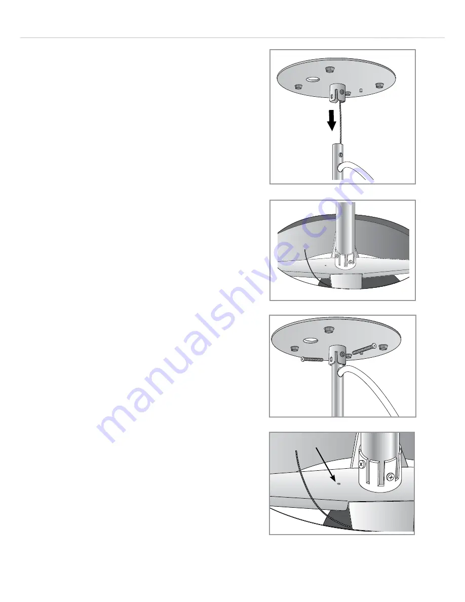
10.   With a second person supporting 

the weight of the sphere, thread 
the safety cable down the tube 
assembly (Fig. 16) so it exits within 
the top cavity of the sphere (Fig. 17).

11.   Insert the top tube into the ceiling 

bracket and secure it with two 
supplied through-bolts and nuts (Fig 
18). 

12.  Pass the end of the safety cable up 

through its hole in the top of the 
sphere (marked “A” in Fig. 19).  Then 
fit the cable clamp to it.

Fig. 18

A

Содержание 3S10BL

Страница 1: ...Care Department The Group Ltd Harby Road Langar Nottinghamshire NG13 9HY T 01949 862 012 F 01949 862 003 E customer care cda eu W www cda eu www cda eu 3S10BL 3S10WH Extractors Installation Use and Ma...

Страница 2: ...pervision or instructions on how to use the appliance by someone who is responsible for their safety Under no circumstances should any external covers be removed for servicing or maintenance except by...

Страница 3: ...rately the product is marked with a crossed out wheeled dustbin Please note This appliance is designed to recirculate air only under no circumstances should it be connected to any ductwork or external...

Страница 4: ...4 Using Your Extractor Remote Control A LED lights B Plus button C Light button D Power button E Clock button F Minus button A E D C B F Fig 1...

Страница 5: ...o switch from a higher speed to the lowest one it is necessary to press the Power button D twice once to switch the motor off then second time to restart it at the lowest speed To switch the light on...

Страница 6: ...ying to a shine with a clean cloth for example the CDA E Cloth Cleaning the grease filters The grease filters should be kept clean to minimise the risk of fire The grease filters may be removed then c...

Страница 7: ...to remove the second set of carbon filter and aluminium grease filter To re fit the aluminium grease filters after cleaning Slide one carbon filter and one aluminium grease filter back into the housin...

Страница 8: ...al filter every four to six months depending on use To replace the charcoal filters The charcoal filters are removed as part of the grease filter cleaning process described on the previous page Refer...

Страница 9: ...has not been switched off 2 Check that the fuse in the spur has not blown 3 There is a hidden on off switch inside the body of the globe Ensure that this has not been accidentally switched off during...

Страница 10: ...OUTLET AND PROTECTED BY A 3A FUSE We recommend that the appliance is connected by a qualified electrician who is a member of the N I C E I C and who will comply with the I E T and local regulations T...

Страница 11: ...ed brown must be connected to the terminal marked L Live or coloured red Note Use a 3A Fuse Assembly and electrical connection should be carried out by specialised personnel When installing this produ...

Страница 12: ...This instruction overrides the instructions supplied with the CDA hob The height should be measured from the top of the hotplates or burners Where the extractor is to be installed above a non CDA hob...

Страница 13: ...his plate to the ceiling using suitable fixings The ceiling fixings supplied with this appliance are designed for fitting to a solid masonry or concrete ceiling If mounting the appliance to any other...

Страница 14: ...meter hanging tube and pre assemble this to the sphere Fig 10 Thread the power cable through the top chrome cover and locate this cover back onto the globe Pass the power cable through the tube ensuri...

Страница 15: ...ugh the smaller diameter hanging tube Important Ensure that the power cable exits through the larger hole in the side of the tube near the top end Fig 13 8 Slide the upper hanging tube inside the lowe...

Страница 16: ...assembly Fig 16 so it exits within the top cavity of the sphere Fig 17 11 Insert the top tube into the ceiling bracket and secure it with two supplied through bolts and nuts Fig 18 12 Pass the end of...

Страница 17: ...shown as in Fig 15 NOTE the security of the height adjusting grubscrews should be double checked at this stage 13 Pull the safety cable tight at the lower end pulling through the hole A in Fig 19 the...

Страница 18: ...18 Notes...

Страница 19: ...19 E O E All instructions dimensions and illustrations are provided for guidance only CDA reserve the right to change specifications without prior notice Notes...

Страница 20: ...F 01949 862 003 E customer care cda eu W www cda eu www cda eu Please contact our Customer Care Department for Service on the details below Customer Care Department The Group Ltd Harby Road Langar No...

Отзывы: