00P6H5000CSEB3
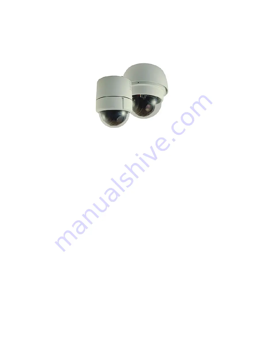
Vandal Proof Mini Speed Dome Camera
Indoor Dome / Outdoor Dome
Installation Guide
Version 1.3
Страница 1: ...00P6H5000CSEB3 Vandal Proof Mini Speed Dome Camera Indoor Dome Outdoor Dome Installation Guide Version 1 3 ...
Страница 2: ...y not be copied photocopied translated reproduced or reduced to any electronic medium or machine readable format in whole or in part without prior written permission of the company Important Information Before proceeding please read and observe all instructions and warnings in this manual Retain this manual with the original bill of sale for future reference and if necessary warranty service When ...
Страница 3: ...nvironment and human health which could otherwise be caused if this product is thrown into the garbage bin The recycling of materials will help to conserve natural resources For more details information about recycling of this product please contact your local city office your household waste disposal service or the shop where you purchased the product Compliance is evidenced by written declaratio...
Страница 4: ...104 F and the outdoor camera under conditions where temperature is between 30 C 45 C 22 F 104 F and humidity is below 90 Do not expose the indoor dome camera to rain or moisture or try to operated it in wet areas The indoor dome camera is designed for indoor use or locations where it is protected from rain and moisture Turn the power off immediately if the camera is wet and ask a qualified service...
Страница 5: ...ng and Connection 19 4 Dome Installation 21 4 1 Optional Accessories 21 4 2 Ceiling Mount 28 4 2 1 Hard Ceiling Mounting Indoor 29 4 2 2 In Ceiling Mounting Indoor 31 4 2 3 In ceiling Mounting with Ceiling Panel 33 4 2 4 Ceiling Mounting with Straight Tube 34 4 3 Wall Mount 35 4 3 1 Wall Mounting with Gooseneck Tube 35 4 3 2 Mini Pendant Mount 36 4 3 3 Wall Box Mounting 38 4 4 Corner Mount 39 4 4 ...
Страница 6: ...Installation Guide 5 5 5 Coaxial Telemetry 49 6 System Integration 50 6 1 Using Pelco Keyboard 50 6 2 Using Philips Allegiant Keyboard 52 Appendix A Technical Specification 53 ...
Страница 7: ...telligent design for easy installation Outdoor Vandal Proof Mini Speed Dome For both indoor and outdoor applications Flexible accessories enable the most effective installations Weather resistant housing and sunshield for harsh environment General Operation Requirements A minimum of one control device is required for operation such as a control keyboard a DVR or a PC The Vandal Proof Dome Cameras ...
Страница 8: ...twork distance up to 1 2 km 4000 feet and to protect the connected devices it is highly recommended to place a repeater at the mid point However a repeater may be needed in the network distance less than 1 2 km if the used cables are not the CAT 5 24 gauge cables see 3 4 4 RS 485 Connector Refer to the repeater s manual for detailed information ...
Страница 9: ...duct and contact your dealer for assistance Indoor Vandal Proof Mini Speed Dome Hard Ceiling Mount and Decoration Ring 12V DC Power Adaptor Power Cord 12V DC Only Dome Body with 4 2 cover Fixing Plate Self tapping Screws Plastic Screw Anchors 50 cm Data Cable for Power Supply Video and RS 485 for 12V DC 50 cm data cable for Power Supply Video and RS 485 for 24V AC Quick Guide CD Operation Manuals ...
Страница 10: ...n Guide 9 Outdoor Vandal Proof Mini Speed Dome Dome Body Data Cable for Power Supply Video and RS 485 Lubricant Screws 5 4 Optical Cover 50 cm 13 pin Alarm Cable Water proof Rubber Quick Guide CD Operation Manuals ...
Страница 11: ...the dome cover and take off the lens cap to prepare for subsequent switch setting Step 1 Unpack the dome package and take out the dome body Step 2 Unscrew the three screws on the dome back as marked in the figure and remove the dome housing with the dome cover Step 3 Remove the PE cloth sheet and take off the lens cap Step 4 Replace the dome housing with the cover back Then screw it and the dome b...
Страница 12: ... about various switch setting 3 2 Preparations for Outdoor Dome Setups This installation procedure is for the outdoor dome equipped with sunshield housing Please follow the steps below to complete dome housing installation STEP 1 Unpack the dome package and take out the dome body STEP 2 Rotate the top holder and take it off from the dome body ...
Страница 13: ...icant on the cover s water proof rubber to make the installation process smoother Note that the tiny protrusion on the dome cover must align with one of the four holes on the dome body STEP 5 Gently pressure the dome cover downward with two hands on the side of it DO NOT press the cover as shown in the figure this might cause damage to the dome body ...
Страница 14: ...e camera to other devices of CCTV system please complete the dome ID and communication switch setting These switches are located on the bottom of the dome camera 3 3 1 Switch Definition Please refer to the following figures and table for switch location and definitions Indoor Dome Outdoor Dome A Reserved B Communication Switch C Dome ID Switch D Dome Control Protocol Switch E RJ 45 Connector for I...
Страница 15: ...and SW 4 they are used for termination and Line Lock adjustment respectively The SW 5 is mainly used when users want to restore the camera to the factory default status moreover once firmware upgrade is carried out users need to reset the SW 6 afterward RS 485 Setting Half duplex Full duplex 3 3 3 Dome ID Setting Please change the dome ID if there is more than one dome on the same installation sit...
Страница 16: ...ces are provided from different manufacturers Use the switch to set your dome control protocol and the baud rate Refer to the table below and turn the arrow to choose a protocol for your speed dome Switch No Protocol Baud Rate 00 VCL 9600 01 Pelco D 2400 02 Pelco P 4800 04 Chiper 9600 05 Philips 9600 07 GANZ PT 9600 08 AD422 4800 09 DM P 9600 11 Pelco D 4800 12 Pelco D 9600 13 Pelco P 2400 14 Pelc...
Страница 17: ...d dome cameras require video and data cables as described below The video cable sends video signals to a remote viewing site Using a coaxial cable to send video signals is recommended RS 485 cable carries commands from a control device to the dome cameras A CAT 5 24 gauge cable is recommended The power cable provides either AC 24V or DC 12V power supply to the dome NOTE Ensure power supply corresp...
Страница 18: ...ted Furthermore when wiring the power cable make sure the G Y wire Ground inserted into the mid pin of the terminal block 3 4 3 22 Pin Connector Definition With the 22 pin connector installers can simply connect the power video and RS 485 cables to the dome at once Particularly the alarm pins are serviceable for connecting alarm input and output devices such as alarm sensors sirens or flashing lig...
Страница 19: ...eo 24AWG 3 4 4 RS 485 Connector RS 485 is the interface that communicates the dome camera and its control device Please connect the control keyboard to the speed dome through the terminal block The recommended cables for RS 485 communication are CAT 5 cables maximum cable length for over 24 gauge wire is 4000 feet 1219 meters If the total cable length exceeds 4000 feet using a repeater to maintain...
Страница 20: ...larm input and output devices The table follows will illustrate the way to wire cords into the connector housing shown in the figures below Please refer to the section 3 4 3 22 Pin Connector Definition for the exact position of each cord Insert the terminal into the pin holes on the connector housing with the hook outward as indicated in the figure Pin Corresponding Pins 22 Pin Connector Definitio...
Страница 21: ...Installation Guide 20 To unlock the terminal press the hook as indicated in the figure with a proper tool and pull it out gently Connect the 22 pin connector to the dome camera ...
Страница 22: ...l Proof Cover Diameter 137 mm 5 4 inches Security Screw Set equipped with Vandal Proof Cover ZCA IPA2 Indoor Mount Kit For mounting the indoor dome camera onto a gooseneck straight tube White Diameter 140 mm 5 5 inches Height 74 mm 2 9 inches 0 3 kg 0 7 lbs Attached Components Waterproof Rubber Hexagon Key Lock Screw Plate M5 8 screw 1 M5 8 security screw 1 M3 6 screw 1 Power Adapter Input 100 115...
Страница 23: ... 24VAC 72VA Input 220 230VAC Output 24VAC 72VA NOTE When wiring make sure the G Y wire Ground inserted into the mid pin of the terminal block Sunshield Outdoor Dome White Color Height 89 9 mm 3 54 inches Diameter 190 mm 7 48 inches 0 15 kg 0 33 lbs Mounting Accessories ZCA HC200A Hard Ceiling Mount For Hard Ceiling use Height 19mm Diameter of three holes 4 5 mm Diameter of the bracket 158 mm 0 2 k...
Страница 24: ...For ceiling mounting Zn platted 610 305 mm 24 12 inches Diameter 155 mm 6 1 inches ZCA GT200 Gooseneck Tube White Color Iron 298 385 mm 11 73 15 56 inches 2 1 kg 4 6 lbs Supplied with rubber washer 8 1 pendant tube washer 1 spring washer 8 1 and waterproof rubber 1 M8 12 screw 1 ZCA GT100 Mini Pendant Mount White 184 104 115 2 mm 7 24 4 09 4 54 inches 0 6 kg 1 2 lbs Supplied with rubber washer 8 1...
Страница 25: ...tube washer 1 spring washer 8 1 and waterproof rubber 1 M8 12 screw 1 Corner Plate Mini For mounting with Mini Pendent Mount White 270 L 166 W 95 D mm 8 7 8 4 6 inches Supplied with washer 8 4 spring washer 4 M8 16 screw 4 M8 nut 4 ZCA CST Corner Standard Mounting Plate White 222 204 117 mm 8 7 8 4 6 inches 2 kg 4 4 lbs Supplied with washer 8 4 spring washer 4 M8 16 screw 4 M8 nut 4 ...
Страница 26: ... 16 screw 4 and spring washer 4 ZCA CWB Corner Wide Box White Ivory 232 234 210 mm 9 1 9 2 8 3 inches 2 7 kg 6 lbs Supplied with washer 4 M8 16 screw 4 and spring washer 4 ZCA PTB Pole Thin Box White Ivory 291 136 242 mm 11 5 5 4 9 5 inches 3 1 kg 6 9 lbs Supplied with M8 16 screw 4 washer 4 spring washer 4 stainless steel straps 4 ...
Страница 27: ... 4 stainless steel straps 4 ZCA WBM Wall Box Mounting Ivory 270 L 166 W 95 D 10 6 6 5 3 7 inches 2 2 kg 4 84 lbs Supplied with M8 16 screw 4 washer 4 spring washer 4 ZCA PTDM Pole Thin Direct Mounting White Ivory 232 136 60 mm 9 1 5 4 2 4 inches Diameter 112 140 mm 4 4 5 5 inches 0 7 kg 1 6 lbs Supplied with stainless steel straps 4 M8 16 screw 4 washer 4 ...
Страница 28: ...kg 0 04 lbs Stainless Strap Cutter For tension cut and crimp stainless steel straps 1 4 kg 3 1 lbs Suitable for straps width 1 2 5 8 3 4 Other Application Accessories Repeater Converter ZCA RS422 485 RS 485 RS 422 Repeater ZCA RS232 485 RS 232 between RS 485 RS 422 ZCA BP 485 Bi phase to RS 485 RS 422 ZCA RS422 485 ZCA RS232 485 ZCA BP 485 ZCA CB Connector Box Indoor Application Recommended for wi...
Страница 29: ...CA COAX Coaxial Telemetry Transmit video and RS 485 control signals via one BNC line Dimension 100 90 28 mm 3 93 3 54 1 1 inches Front View Rear View 4 2 Ceiling Mount Generally there are three kinds of dome camera ceiling mounting methods hard ceiling in ceiling and mounting with straight tube Refer to the following sections for more details The following figures show how cables connect to the do...
Страница 30: ...d items are all in the dome camera package Items Needed Dome Camera Hard Ceiling Mount and Decoration Ring Supplied Fixing Plate Supplied Tools Needed Tool for drilling Screw Drive Follow the steps to install the high speed dome camera for hard ceilings STEP 1 Screw the Fixing Plate to your dome body STEP 2 Remove the Hard Ceiling Mount from the Decoration Cover STEP 3 Attach the Mount to the ceil...
Страница 31: ...the dome body NOTE If use an IP dome a network cable is needed other than the data cable In addition the length of the network cable should be no longer than 2 cm STEP 7 Attach the dome body to the Mount and rotate the dome body clockwise Tighten the fixing screw on the fixing plate STEP 8 Assemble the Decoration Ring to the Mount ...
Страница 32: ...era T Bar Optional Accessory Supplied Screw Equipped with T Bar Red Sticker Equipped with T Bar Decoration Ring Supplied Tools Needed Tool for cutting a circle on the ceiling Screw Driver Follow the steps to install the integrated high speed dome camera with T Bar Ceiling mount accessory for in ceiling mounting STEP 1 Screw the T Bar Body Holder which is equipped with the T Bar onto the dome back ...
Страница 33: ...wings should be inward when putting up the T Bar into the ceiling hole as shown in the picture STEP 4 Rotate the T Bar s wings to fix the T Bar at the edge of the ceiling opening STEP 5 Tighten the screws on the wings STEP 6 Connect the data cable to the dome body through the center hole of the bracket NOTE If use an IP dome a network cable is needed other than the data cable ...
Страница 34: ...sure the dome body fastened firmly and screw the T Bar Body Holder STEP 8 Assemble the Decoration Ring to the T Bar Completion 4 2 3 In ceiling Mounting with Ceiling Panel To mount the dome camera to a suspended ceiling with the T Bar the ceiling panel could be employed as shown in the figure below ...
Страница 35: ... accessory for the outdoor dome Screws and Screw Anchors for fixing the straight tube onto the ceiling not supplied Tools Needed Tool for drilling Tool for screwing Follow the steps to mount the dome with the straight tube 1 Ensure that the ceiling can support the weight of the dome camera and straight tube 2 Make a cable entry hole on the ceiling 3 Fix the Straight Tube to the ceiling with proper...
Страница 36: ...ng Mount Straight Tube Waterproof Rubber 4 3 Wall Mount 4 3 1 Wall Mounting with Gooseneck Tube The following figures show how cables run through the tube in different ways Cables exposed Cables recessed Items Needed Dome Camera Gooseneck Tube and other equipped items optional accessory Waterproof Rubber standard accessory for the outdoor dome ...
Страница 37: ...ubber to the gooseneck tube 4 Thread the cables through the gooseneck tube and the top holder 5 Fix the top holder to the gooseneck tube with the supplied screws and washers Then adjust the waterproof rubber to the junction of straight tube and top holder 6 Connect the cables to the dome camera Then attach the dome to the top holder and fix them with the supplied screw Wall Mounting Gooseneck Tube...
Страница 38: ...d block the cable entry hole with the supplied sponge in two ways See the illustrations below 3 Thread the cables through the Mini Pendant Mount and fix the pendant mount on the wall with proper screws and screw anchors not supplied 4 If use an outdoor dome attach the waterproof rubber to the Mini Pendant Mount 5 Thread the cables through the top holder and fix it to the Mini Pendant Mount with th...
Страница 39: ...the gooseneck tube and wall box 1 Fix the Wall Box on wall with proper screws and screw anchors not supplied 2 Fasten the gooseneck tube on the wall box with the supplied screws and washers 3 Attach the waterproof rubber to the gooseneck tube 4 Thread the cables through the gooseneck tube and the top holder 5 Fix the top holder to the gooseneck tube with the supplied screws and washers Then adjust...
Страница 40: ...unting Plate optional accessory Waterproof Rubber standard accessory for the outdoor dome Screws and Screw Anchors for fixing the Corner Standard Mounting Plate not supplied Tools Needed Tool for drilling Tool for screwing Follow the steps below to mount the dome camera with the corner standard mini mounting plate and gooseneck tube mini pendant mount 1 Make a cable entry hole on the wall to reces...
Страница 41: ...e mini pendant mount and top holder 7 Connect the cables to the dome camera Then attach the dome to the top holder and fix them with the supplied screw Corner Wall Mounting Corner Standard Mini Mounting Plate Gooseneck Tube Mini Pendant Mount Waterproof Rubber 4 4 2 Corner Thin Wide Box Mounting The corner thin wide box is designed to be installed with a gooseneck tube Items Needed Dome Camera Goo...
Страница 42: ...washers 4 Attach the waterproof rubber to the gooseneck tube 5 Thread the cables through the gooseneck tube and the top holder 6 Fix the top holder to the gooseneck tube with the supplied screws and washers Then adjust the waterproof rubber to the junction of straight tube and top holder 7 Connect the cables to the dome camera Then attach the dome to the top holder and fix them with the supplied s...
Страница 43: ...e Direct Mounting on a pole with equipped stainless straps 2 Fix the gooseneck tube on the pole direct mounting with the supplied screws and washers 3 Attach the waterproof rubber to the gooseneck tube 4 Thread the cables through the gooseneck tube and the top holder 5 Fix the top holder to the gooseneck tube with the supplied screws and washers Then adjust the waterproof rubber to the junction of...
Страница 44: ...Fasten the Pole Thin Wide Box on a pole with equipped stainless straps 2 Fix the gooseneck tube on the pole box with the supplied screws and washers 3 Attach the waterproof rubber to the gooseneck tube 4 Thread the cables through the gooseneck tube and the top holder 5 Fix the top holder to the gooseneck tube with the supplied screws and washers Then adjust the waterproof rubber to the junction of...
Страница 45: ...connection between alarms cameras and other devices for easy installation To connect the connector box with other devices Use a RS 485 cable CAT 5 is recommended to complete RS 485 communication wiring with control devices such as DVRs and Control Keyboards Use a 22 pin cable to connect the connector box to the dome For more detailed information please refer to the connector box user s manual ...
Страница 46: ...sers can either connect one dome camera to one power box and to Internet or to other control devices DVR Control Keyboard and monitors as shown in the diagrams below For more detailed information please refer to the power box user s manual Connecting the Dome to the Power Box and Internet Connecting the Dome to the Power Box and Various Control Devices NOTE One power box can only be connected to o...
Страница 47: ... between devices If a converter repeater is used the total network distance of the surveillance system can be extended and the connected devices will also be protected Up to 10 devices are allowed to connect to each repeater For more detailed information please refer to the converter repeater user s manual RS 485 RS 422 Repeater RS 232 between RS 485 RS 422 Bi Phase to RS 485 RS 422 Indoor Dome Ap...
Страница 48: ...Installation Guide 47 Outdoor Dome Application ...
Страница 49: ...ing with cameras up to 1 0 kilometers away Additionally the SDU can be installed in either star or daisy chain configuration with up to 160 cameras see the diagrams below Its versatile installation configuration makes an easy integration into expanding surveillance systems For more information please refer to the SDU user s manual Star Configuration Daisy Chain Configuration ...
Страница 50: ...ras and controlling devices e g DVR and keyboard It simplifies the work of wiring by transmitting video and RS 485 control signals via one BNC line so that to bring users economical benefits The following is the coaxial telemetry application diagram For more information please refer to the coaxial telemetry s quick installation guide ...
Страница 51: ...lay the OSD menu ENTER Iris Open 9 5 hold Preset To send a ENTER command press Iris Open or 9 5 hold Preset Set and execute PRESET Hold Preset To set Preset hold the key Preset Preset To execute a preset position press the key Preset Set and execute SEQUENCE By OSD To set Sequence please enter the OSD and go to the Preset setting menu 7 0 7 8 Preset The following Presets allows you to execute Sequ...
Страница 52: ...cables maximum cable length for over 24 gauge wire is 4000 feet 1219 meters If the total cable length exceeds 4000 feet using a repeater to enlarge the signals is recommended Cable Definition P Protocol Keyboard to the PTZ Camera For P Protocol Keyboard For SpeedDome 1 2 4 5 6 7 8 Tx Tx 12V GND Rx Rx 1 2 3 4 5 6 Tx Tx 12V GND Rx Rx Cable Definition D Protocol Keyboard to the PTZ Camera For SpeedDo...
Страница 53: ...preset position set Set preset position Special Function 7 6 set Exit the OSD menu directly 7 7 set 1 Display or hide the OSD menu 2 A virtual key to issue an ENTER command when the OSD is displayed 7 8 set Reset the doma camera Iris Open Send an ENTER command when the OSD is displayed Control Dome Camera Using Allegiant Keyboard Users can move the cursor left right up down through pushing the joy...
Страница 54: ...0 Tilt Travel 10 100 Manual Speed 0 5 55 s Presets 256 Pan 0 5 F Type Motor 0 125 G Type Motor Preset Accuracy Tilt 0 5 Pan 5 300 s Preset Speed Tilt 5 300 s Cruise 1 Sequence 8 Auto Pan 4 Proportional Pan Tilt On Off Pan and tilt speed proportional to zoom ratio Resume after Power loss Yes Zone Title 16 Home Function Preset Sequence Auto pan Cruise Auto Flip Mechanical Off Day Night IR Cut Filter...