background image


1.


Product Description 

1.1


General description 


Fig. 1 

Wheelchair transformer CaterWil GTS3 with electrical drive is designed to be driven by disabled 

person or by the attendant. The wheelchair can overcome different kind of obstacles including stairs.  

CaterWil has wheels and tracks platform. Wheels platform is used for moving on a smooth 

surface. Track platform is needed for overcoming stairs, curbs and other obstacles. In a wheel mode 
the track platform is hidden in its upper position doesn’t slug and doesn’t create resistance for moving. 
When the button pressed on a remote control the linear actuator is activated and though the 
mechanical system of levers the track platform goes down. Caterpillars are moved by the motors that 
rotate the wheels but using the additional gear that provides higher torque and lower speed on stairs. 


The passenger’s seat is installed on hinges and turned by the separate drive. Turning the seat 

is important when going up and down the stairs for displacing the center of mass and saving a vertical 
position of the passenger that is safe and comfortable. The seat is controlled by electronics in 
automatic cycle. Three axis sensors accelerometers determines the position of the main platform and 
the seat, using the acquired data system smoothly turns the seat leaving it’s constant 

position relative 

to the horizon. 

  The power supply of the system is provided by 

batteries. Two main drives (left and right) that 

rotate wheels or tracks (depends on moving mode) are made as DC gear-motors. Each of three linear 
actuators is made as a DC motor driving a rod via a gear system. The actuators strokes are limited by 
limit switches. 

Содержание GTS3

Страница 1: ...1 Wheelchair transformer CaterWil model GTS3 Instructions for Use Caterwil LLC phone 7 383 319 7837 www caterwil com ver 1 0 1 rev 25 01 2017...

Страница 2: ...protection 8 2 Start up and restarting instructions 8 2 1 Installing footrests 8 2 2 Adjusting the Lower Leg Length see fig 5 9 2 3 Adjusting footrest angle see fig 5 9 2 4 Adapting the Remote contro...

Страница 3: ...s that rotate the wheels but using the additional gear that provides higher torque and lower speed on stairs The passenger s seat is installed on hinges and turned by the separate drive Turning the se...

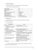
Страница 4: ...tracks and can climb ramps up to 18 deg on wheels fig 2 1 2 Technical specifications Table 1 Wheelchair specifications Characteristic Unit Value Notes 1 Dimensions length x width x height mm 1200 140...

Страница 5: ...to enter driving commands and to display the current state of certain functions and components fig 3 1 Chair down button 2 Chair up button 3 Track mode button 4 Special functions button 5 On Off butto...

Страница 6: ...e power wheelchair off Horn button The horn will sound as long as the horn key is being pressed Speed up and down buttons Pressing the speed buttons shortly increases or reduces the speed level After...

Страница 7: ...kes and emergency brakes 3 40A fuse For overload or short circuit prevention 4 Battery charge indicator For battery discharge prevention 5 Emergency stop when Remote controller communication is failed...

Страница 8: ...here is no need to use personal ESD protective equipment 1 8 Materials safety The chair and accessories are made of non harmful non allergic materials that has no limitations for contact with human sk...

Страница 9: ...justing footrest angle see fig 5 To elevate the footrest 1 Use the release lever on the footrest 2 Move the footrest to the desired position 3 Let go of the release lever Fig 5 2 4Adapting the Remote...

Страница 10: ...height to the arm length of the user you must loosen two clampers on the armrest holder see fig 6 You can now slide the armrest up and down 2 7Lap Belt The GTS3 can be equipped with a lap belt To appl...

Страница 11: ...the wheelchair off when finished NOTICE There is no need to press ESD button to turn off the wheelchair during normal operations Press the ESD button for emergency stop only 3 Maintenance Manual 3 1...

Страница 12: ...wires from installed batteries 3 Remove batteries from the battery box 4 Install new batteries into the battery box 5 Screw wires on new batteries as on the fig 10 Red wire to the red terminal black...

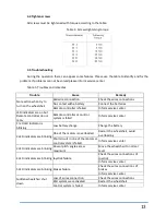
Страница 13: ...e controller or control system is failed Inform service center 1 red LED indicator is blinking Low battery charge Charge the battery 2 LED indicators are blinking One of the motors is overloaded Resta...

Отзывы: