3. Examine Sleeves for scoring or etching and replace.
Immerse sleeves (D) in oil and carefully twist and
push sleeve onto rod with machined counter bore
end first (E).
4. Install Seal Retainers. If Wicks are used, replace Wicks,
thoroughly saturate with oil, place in Seal Retainer and
install retainer.
5. Place Inlet Manifold on pair of clearance blocks with
crankcase side down and drive out old seals.
6. Invert Inlet Manifold with crankcase side up and install
new Seals. Lubricate O.D. of Seal and install
Prrrrm-A-Lube Seal with garter spring down. If using
blue dot seal, install blue dot seal facing up.
NOTE: When using alternate materials, the fit of the
special materials may be snug and require gently
driving the LPS into position with a cylinder of the
same diameter to assure a square seating and no
damage to the LPS.
NOTE: 25FR and 60FR do not have Prrrrm-A-Lube
option. Install with spring down.
7. Slip lubricated Seal inserters onto Piston Rod ends,
position Inlet Manifold onto pump and remove Seal
inserters. Some models secure Inlet Manifold to
crankcase. Replace fasteners and torque per chart.
8. Reassemble Piston Assemblies and Discharge
Manifold as described.
9. Replace original quantity of Shims on each stud before
replacing Discharge Manifold. Refer to Tech Bulletin 017.
■
Hi-Temp Models
On the Model 2520C series, the Seal with the lip, the
adapter and the Seal with grease pocket can be driven
from the Inlet Manifold.
To install a new Seal assembly, place Manifold on work
surface with crankcase side up. Install new seal with lip
in chamber with garter spring down. Next examine
O-Ring and Adapter and replace either if worn. Lubricate
outer surface of Adapter and install new O-Ring. Press
Adapter into chamber, smaller diameter end first. Next
install grease pocket seal with garter spring down. Then
proceed with standard reassembly of pump.
4 BOLT MFLD
8 BOLT MFLD
1
3
7
1
3
5
4
2
6
4
2
8
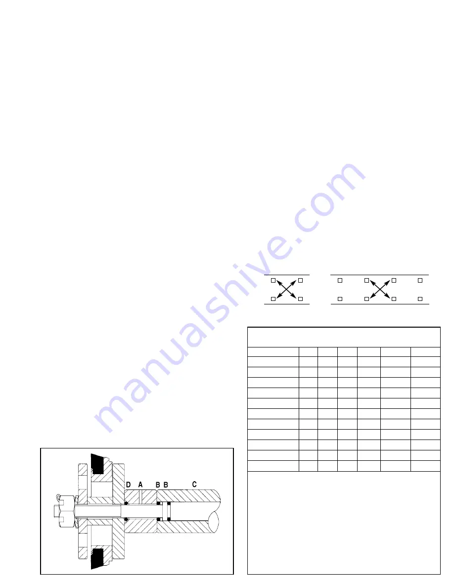
The hi-temp models also have a special vented Inlet
Valve Spacer (A) Following the installation of the Piston
Rod O-Rings (B) and Sleeve (C), slip this vented Spacer
onto the Rod with the tapered end forward. Then install
O-Ring (D) in the tapered groove and proceed with
standard Piston Assembly.
SERVICING CRANKCASE SECTION
1. While Inlet Manifold, Sleeves and Seal Retainers are
removed, examine Crankcase Seals for wear.
2. Check oil for proper level and for evidence of water in
the oil. Change crankcase oil on a reqular schedule.
See Preventative Maintenance Check-List.
3. Rotate Crankshaft by hand to feel for smooth bearing
movement.
4. Examine Crankshaft Oil Seal externally for drying,
cracking or leaking.
5. Consult your local CAT PUMPS supplier if Crankcase
Service is required.
TORQUE SEQUENCE
PREVENTATIVE MAINTENANCE CHECK-LIST
Check
Daily Weekly 50 hrs. 500 hrs.* 1500 hrs.** 3000 hrs.**
Clean Filters
x
Oil Level/Quality
x
Oil Leaks
x
Water Leaks
x
Belts, Pulley
x
Plumbing
x
Initial Oil Change
x
Oil Change
x
Seal Change
x
Valve Change
x
Accessories
x
* If other than CAT PUMPS special multi-viscosity ISO68 oil is used,
change cycle should be every 300 hours.
** Each system’s maintenance cycle will be exclusive. If system
performance decreases, check immediately. If no wear at 1500
hours, check again at 2000 hours and each 500 hours until wear is
observed. Valves typically require changing every other seal change.
Duty cycle, temperature, quality of pumped liquid and inlet feed
conditions all effect the life of pump wear parts and service cycle.
** Remember to service the regulator/unloader at each seal servicing
and check all system accessories and connections before resuming
operation.


