background image

28 


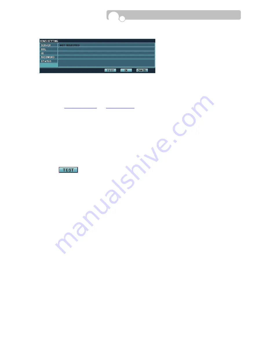
DDNS SETTING 


Dynamic DNS(DDNS) allows you to create your own domain name that points to your dynamic IP or static  
IP address or URL.  


1.


Visit free DNS service providers in the internet and create your domain name. (Currently, the DVR  

 supports 

www.dyndns.com

 and 

www.no-ip.com

.) 


2.


SERVER : Select the DNS service provider 


3.


URL : Set the domain name that has been registered with the DNS service provider. 


4.


ID : Set the ID registered with the DNS service provider. 


5.


PASSWORD : Set the password Password registered with the DNS service provider. 


6.


Click             button to test whether the DDNS setting has been set up correctly. 


7.


STATUS : A message will appear informing the user whether the DDNS setting has been set up 

                      correctly. 


Configuration

Содержание CDVR-0404R

Страница 1: ...Operation Manual Digital Video Recorder CDVR SERIES ...

Страница 2: ...l interference in which case the user will be required to correct the interference at his own expense CAUTION The installation of this product should be made only by qualified technicians and should conform to all local codes WARNING To reduce a risk of fire or electrical shock do not expose this product to rain or moisture The product described in this document is in compliance with the requireme...

Страница 3: ...le operation of the product and to protect it from overheating and these openings must not be blocked or covered The openings should never be blocked by placing the product on a bed sofa rug or other similar surface This product should not be placed in a built in installation such as a bookcase or rack unless proper ventilation is provided or the manufacturer s instructions have been adhered to 10...

Страница 4: ...ck Upon completion of any service or repairs to this product ask the service technician to perform safety checks to determine that the product is in proper operating condition 17 Heat The product should be situated away from heat sources such as radiators heat registers stoves or other products including amplifiers that produce heat the product 18 Internal Fan The internal fan rotates at high spee...

Страница 5: ...on 3 10 Log List 3 11 Backup 4 OPERATION 4 1 Monitoring 4 1 1 Multi Screen Display 4 1 2 Changing Channel 4 1 3 Freeze Screen 4 1 4 Full Screen Display 4 2 Monitoring Control 4 2 1 Multi ScreenDisplay 4 2 2 Video 4 2 3 Audio 4 2 4 etc 4 3 Playback Search 4 3 1 Time Date Search 4 3 2 Event Search 4 3 3 File Search 4 3 4 Capture Image Capture Video Clip Copy 4 4 PTZ Control 4 5 Recording Panic Recor...

Страница 6: ...o not attempt to use the unit contact the supplier immediately If the unit must be returned it must be shipped in the original packing box Remote Controller Operation Manual l Mouse Power Cable CMS Program 1 INTRODUCTION Digital Video Recorder Rack Mount Bracket 2pcs Size AAA Batteries 2pcs Hard Drive Screws 12pcs ...

Страница 7: ...on the screen 7 Enter the PTZ control mode 8 Enter the Setup Mode 9 Clear the Monitoring Control Menu Return to a higher Category Group Field Cancel the selected Field button 10 Insert and Eject CD You may also push the tray to insert the tray 11 Operation Keys Activate a function or complete an entry that you have made during setup Display the Monitoring Control Menu on the screen Move between ca...

Страница 8: ...EO Connector Connection to S Video jack 4 SENSOR ALARM PTZ Terminal Connect G Ground before connecting the sensors Connect the alarm devices in its corresponding numbers Connect the PTZ Speed Dome Camera 5 LAN Port 10 100 Base T RJ45 ethernet port for network connection Introduction CDVR 0404R 1 2 3 4 SENSOR ALARM PTZ G G 1 2 3 4 ...

Страница 9: ...or vice versa while the DVR is in operation press the Monitor button on the front panel once If both Composite and S Video output is connected priority will be given to S Video 7 RS 232 Port Serial port for Keyboard Controller and POS interface 8 VIN1 VIN4 Video Input Connectors Input connectors for video signals 9 VOUT Connector Output connector for Composite video output 10 SPOT Connector Output...

Страница 10: ...to monitor 4 VOUT AOUT Connectors Output connector for video VOUT and audio AOUT signals 5 AUDIO INPUT Connectors Input connectors for audio signals 6 VIDEO INPUT Connectors Input connectors for video signals 7 ALARM Output Terminal Connect the alarm devices in its corresponding numbers 8 LOOP OUT Termination switch must be turned on when using loop out 9 VGA Monitor Port Connection to PC monitor ...

Страница 11: ... CD Boot Off CD Boot Test Off Factory Test Mode Color System NTSC PAL When using Composite or S Video output the DVR will auto detect the output when the DVR is Turned on When changing the Monitor Output from Composite to S Video or vice versa while the DVR is in operation press the Monitor button on the front panel once If both Composite and S Video output is connected priority will be given to S...

Страница 12: ...yback Fast reverse playback Playback in reverse forward direction Fast forward playback FULL SCR Change to full screen display during Playback Playback in slow motion 1 2x 1 4 1 8x 1 16 SPEED Increase Decrease speed during playback CH Change channels during Monitoring PTZ Control Playback DISPLAY Change multi screen display type ZOOM Adjust zoom of PTZ camera Toggle between zoom 2x and normal view...

Страница 13: ... bracket using 4 screws and connect the Power Plug and E IDE Cable into the HDD connectors Adjust the Jumper Pin of the HDD to the Master or Slave position before installing the HDD Fasten 2 screws on each side of the HDD bracket to fix the bracket to the DVR bottom 2 INSTALLATION Compatible Hard Disk Drives Samsung Maxtor Fujitsu Seagate Hitachi Western Digital hard disk drives are NOT compatible...

Страница 14: ... of the Hard Drive to the Master or Slave position Fasten 2 screws on each side of the HDD bracket to fix the Hard Drives to the bracket Fasten 2 screws on each side of the HDD bracket to fix the bracket to the DVR bottom Cable Connection Connect the Power Cable and E IDE Cable to each Hard Drive The DVD RW must be connected with the Secondary Slave E IDE Cable and Power Cable Primary Slave Above ...

Страница 15: ...atted recording will start after the formatting is completed Installation S M A R T Self Monitoring Analysis and Reporting Technology S M A R T is a reliability prediction technology to anticipate the failure of a hard disk drive with sufficient notice to allow a system or user to back up data prior to a drive s failure If the controller detects problems in the disk drive reliability it will relea...

Страница 16: ...ring up the Menu bar on to the monitoring screen Click the mouse left button on the button on the right hand corner of the Menu Bar to escape from the Administrator Mode This will prohibit any other users other than the authorized personnel with proper password to enter PLAY Search PTZ Control and SETUP Menu Bar Installation Default value of the Password is set at 0000 Password can be changed in t...

Страница 17: ...ceed automatically once the Firmware CD is inserted The CD will eject automatically once the installation is completed 4 Take out the CD and adjust the DIP Switch CD Switch to the Off position Up The DVR will automatically re boot 5 Repeat the above procedure if the DVR fails to re boot 2 5 USB Flash Drive This DVR supports Hi Speed USB 2 0 Flash Drives Use of Full Speed USB 2 0 Flash Drives may r...

Страница 18: ...EM NTSC PAL DRIVER FULL SCREEN MODE S W VERSION BAUD RATE OUTPUT DWELL TIME ALARM UPGRADE SETUP F W BMP DATA BIT FACTORY DEFAULT RESET PARITY STOP BIT NETWORK RECORD SCHEDULER IP TYPE RESOLUTION SCHEDULE PORT WEB PORT WATERMARK SETUP CONTINUOUS IP ADDRESS RECORD TIME STAMP MOTION GATEWAY AUDIO RECORD MOTION SENSOR SUBNET MASK QUICK RECORD SETUP SENSOR DNS SERVER FPS RECORDING SPEED NONE SMTP SERVE...

Страница 19: ...RE ALARM 5 SENSOR COLOR DIFFUSION Composite Mode SMART FAILURE RECORD BACKGROUND DISPLAY VGA Mode FORMAT CAMERA VGA DE INTERLACE DEVICE INFORMATION LAN SPOT OUT DEVICE BACKUP SEQUENCE DWELL TIME SIZE SETUP SENSOR ACTIVATION TEMPERATURE TIME CAMERA LINK RAW READ ERROR RATE MOTION RE ALLOCATED SECTOR COUNT CHANNELS SPIN UP TIME CALENDAR BACKUP FORMAT BACKUP Configuration ...

Страница 20: ...r approx 3 seconds for the language field to change ID 0 Assign an ID number for the DVR When using several DVRs each DVR will be differentiated with this ID number Input Range 0 255 Use pop up Key Panel or turn the mouse wheel to change the number DATE TYPE DD MM YYYY Select DATE indication method YYYY MM DD MM DD YYYY DD MM YYYY Turn the mouse wheel to change the Date Type TIME DATE Adjust the T...

Страница 21: ...SC PAL Displays the current Color System selected for the DVR Setting values NTSC PAL The DIP Switch in the DVR rear panel should be positioned to the Color System applicable in your region before turning on the DVR power S W VERSION Displays the installed Software version of the DVR UPGRADE Upgrade Setup Values Firmware and BMP Image GUI files Setup Information DVR Firmware Image files used in th...

Страница 22: ...r all designated areas Designate certain parts of the screen for Motion Detection Select the camera number and designate the Motion Detection area using the buttons Designate Motion Detection Area by clicking on the desired areas in the view screen Re clicking on the designated area will cancel the designation Designated area will be highlighted in hazy blue Click to designate the entire area Clic...

Страница 23: ...op up Key Panel or turn the mouse wheel to change the input values Click to test whether the PTZ camera is operating properly after setting the parameters If the PTZ is connected correctly the camera will move to the left every time the button is clicked Click to save the new setting or to cancel the new setting SERIAL SETTING Assign the Driver Baud Rate Data Bit Parity Stop Bit for the selected C...

Страница 24: ...the Alarm that will activate when the Sensor is triggered Click the Alarm that is to be linked to the Sensor OPERATION TIME 0 24 Set the Time for which the Alarm will operate Input Range Between 0 24 Unit Hour Click the time field and turn the mouse wheel to change the time Only the hour can be changed FULLSCREEN MODE OFF Select the Monitoring Screen Display type when the Sensor is triggered OFF N...

Страница 25: ...1 1 Camera and Alarm link the activated camera view will appear in single channel Full Screen Display mode for 5 seconds and the DVR internal buzzer will beep for 3 seconds Turn the mouse wheel to select between OFF and ON OUTPUT DWELL TIME 0 Set the length of time you want the Alarm activated when Motion is detected Input Range 0 600 Seconds Turn the mouse wheel to change the Output Dwell Time Ma...

Страница 26: ... number for web CMS purpose Input Range 0 65000 Use the pop up Key Panel or turn the mouse wheel to input the numbers IP ADDRESS 192 168 123 98 Set the IP Address Input Range for each field 0 255 Use the pop up Key Panel or turn the mouse wheel to input the numbers GATEWAY 192 168 123 254 Set the Gateway Address Input Range for each field 0 255 Use the pop up Key Panel or turn the mouse wheel to i...

Страница 27: ...ID required for PPPOE networking Max 128 characters can be used Use the pop up Key Panel to input characters PPPOE PASSWORD 0000 Set the Password required for PPPOE networking Max 128 characters can be used Use the pop up Key Panel to input characters DVR NAME SERIAL No Assign a Name for the DVR Max 50 characters can be used Use the pop up Key Panel to input characters DDNS SETTING Perform DDNS se...

Страница 28: ... www no ip com 2 SERVER Select the DNS service provider 3 URL Set the domain name that has been registered with the DNS service provider 4 ID Set the ID registered with the DNS service provider 5 PASSWORD Set the password Password registered with the DNS service provider 6 Click button to test whether the DDNS setting has been set up correctly 7 STATUS A message will appear informing the user whet...

Страница 29: ...me Stamp or not Click on the Check box The check box will be highlighted in Orange color when applied AUDIO RECORD ALL Select Audio Recording channels Click on the Audio Channel buttons The selected channels will be highlighted in pink QUICK RECORD SETUP DAYS Enter the total number of days that recording is required and the DVR will automatically set the FPS Recording speed level to achieve that t...

Страница 30: ... wheel to change the quality level PRE RECORDING TIME 0 Seconds Set the Pre Event recording time when Sensor Motion is activated Input Range 0 10 Seconds Turn the mouse wheel to adjust the time POST RECORDING TIME 0 Seconds Set the Post Event recording time for Sensor Motion recording Input Range 10 600 Seconds Turn the mouse wheel to adjust the time WATERMARK is a technology which overlays hidden...

Страница 31: ...or Select the Recording Condition for each Day and Time CONTINUOUS Red Record continuously MOTION Light Yellow Start recording when motion is detected MOTION SENSOR Blue Start recording when MOTION and SENSOR is activated SENSOR Purple Start recording when SENSOR is activated Do not record White Click on the small square buttons on the Weekday Time Table to change the recording condition Apply the...

Страница 32: ... Turn the mouse wheel to change between NORMAL CAMEO MULTI DISPLAY MODE SEQUENCE DWELL TIME 10 Set the time a camera or group of cameras are displayed before changing to the next camera or camera group Input Range 1 600 Seconds Turn the mouse wheel or use the pop up Key Panel to change the dwell time VIDEO ADJUSTMENT BACKGROUND DISPLAY 3 The Background Display color in the setup input fields can b...

Страница 33: ... 600 Seconds Turn the mouse wheel or use the pop up Key Panel to change the dwell time SPOT OUT SENSOR ACTIVATION Disable Set whether to use Spot output when sensor is triggered Click on the check box to enable disable SPOT OUT CAMERA ALL Select the cameras that is to be displayed on the Spot monitor Click ALL or individual channel buttons Configuration ...

Страница 34: ... check box to enable disable SMART FAILURE Select the notification method when SMART HDD Failure occurs BEEP Beeper in the DVR will be activated MAIL E Mail will be transmitted to the designated person Click on the check box to enable disable DEVICE INFORMATION Select the storage device to check the device information and status Device Type Memory Size Temperature Raw Read Error Rate Re Allocated ...

Страница 35: ... Recording Start Stop Log list of Camera On Off or video loss Log list of Network connections Log list of Backup Copy Capture executions Log list of Log In Out informations Log list of System Clock adjustments Log List of Motion Detection Recordings Click on the relevant event button The selected event button will be highlighted in pink CHANNEL Select the channel for Sensor Camera and Motion event...

Страница 36: ...ct the HDD and select the files to be copied by clicking on the check box beside each files A check sign will appear in the check box when selected Re click the check box to cancel the selected file After the files have been selected select the external storage and click on the START button Selected buttons will be highlighted in pink USB Memory Device must be formatted in the FAT32 file system an...

Страница 37: ...ick the mouse wheel to change the multi screen display type 4 1 2 Changing Channel In the 13 channel multi screen mode the channels in the center screen will change CDVR 1608R only Turn the mouse wheel to increase and decrease channels 4 1 3 Freeze Screen You may freeze a live image during monitoring The freeze icon will appear on the selected channel screen Place the mouse cursor on the screen Ch...

Страница 38: ...elected to be viewed in Full Screen during multi screen monitoring Place the mouse cursor on the screen Channel and click the mouse left button In order to return to the previous multi screen monitoring mode re click the mouse left button Operation ...

Страница 39: ... 4 2 1 Multi Screen Display Single Screen Multi Screen Display types and Sequence Display can be selected from the Sub Menu of the Monitoring Control Bar In the 13 channel Multi Screen display type the middle screen is used for sequence display of all channels or display of a selected channel CDVR 1608R only Multi Screen Display Click the MULTI button and click on the multi screen display type you...

Страница 40: ...s and recording in progress GREEN Selected channel Click the VIDEO button and the channel buttons will appear in the sub menu Click the channel button you wish to see 4 2 3 Audio Displays the current status of each audio channels and you may select which audio channel you wish to hear Current status of each audio channels are displayed based on different colors BLUE No recording is in progress PIN...

Страница 41: ... Panel and click to turn off the alarm 2 Change OSD On Screen Display You may select to display or hide OSD on the screen during monitoring Click the button and the OSD will change in the following order HDD Hard Disk Status Bar Disk Capacity Disk Status and Used Capacity Total Capacity information is displayed in the Status Bar HDD1 152G STATUS EXCELLENT The Status bar will disappear automaticall...

Страница 42: ...cording are displayed on the Status Bar When a Sensor is triggered the corresponding Alarm Output will be highlighted in pink When a Network connection occurs the icon will be highlighted in pink The Status Bar will pop up automatically when a Sensor is triggered or Network connection occurs The Status Bar can be cleared by clicking the button 5 GUI Graphic User Interface Transparency Adjustment T...

Страница 43: ...e search method from the Sub Menu Time Date Search Event Sensor Search File Search 4 3 1 Time Date Search Recorded video may be searched based on Time Date 1 Calendar Select the date Dates containing recording data will be highlighted in orange and the selected date will be highlighted in green The current day will be highlighted in blue Move to previous next month by clicking the buttons on the c...

Страница 44: ...t the video clip 3 Playback Scroll Bar Displays the playback progression rate of the selected video clip The scrollbar represents one hour and each scale mark represents 10 minutes Return to the beginning of the selected video clip during playback and playback will not resume unless otherwise instructed If this button is clicked at the beginning of the video clip it will move back to the previous ...

Страница 45: ...button is re clicked Frame by frame forward playback Frame by frame reverse playback Only I Pictures Slow playback 1 2x 1 4x 1 8x 1 16x 5 Time Search Playback Information Channel Date and Time Information of the video clip being played will be displayed in this window A new Date and Time can be entered directly in the field to perform search Click on the Channel Date or Time field and turn the mou...

Страница 46: ...sappear from the screen Return to the Playback Search screen New search can be performed by changing the Date and Time from the menu Click on the scroll bar to move to a different period or use the playback buttons to search the video Operation ...

Страница 47: ... and the selected date will be highlighted in green Move to previous next month by clicking the buttons on the calendar Then click the relevant day 2 Event Select an event and the corresponding channel or channels The selected channel will be highlighted in green Click on the event and select the channel button or buttons Re clicking the button will enable disable the channel 3 Event List Select a...

Страница 48: ...icking the buttons on the calendar 2 Device Select the storage device Click on the storage device button The selected device will be highlighted in Yellow Connected device will be highlighted in blue 3 File List Select a file Based on date you wish to view Move to the previous page of the File List Move to the next page of the File List Click on the file you wish to view and use the playback butto...

Страница 49: ...proximately 5 seconds before and after the designated image will be copied to the storage device 2 VIDEO CLIP COPY This function is to copy a video clip to a DVD RW or USB Memory Mark the Starting Point of the video clip to be copied Mark the Ending Point of the video clip to be copied Start the copying process to the storage device Cancel the capture process Operation Playback Information Backup ...

Страница 50: ... Click to start the copying process or click to stop the copying process or Clear the Start and End period 6 Click to make the menu disappear Moving the mouse cursor to the bottom of the screen or clicking the mouse right button will make the menu reappear on the screen 7 Click to escape from the video clip copy mode and return to the playback screen You may return to the live monitoring screen wh...

Страница 51: ...ERA SETUP before it can be used 1 VIDEO Channel Selection Select the channel Cameral by clicking on the channel buttons in the sub menu bar or directly clicking on the screen of the relevant channel Selected channel button will be highlighted in green 2 PTZ Control Pan Tilt Zoom Focus Iris Adjustment can be performed with these buttons ZOOM Use to Zoom In and Zoom Out FOCUS Use to adjust Focus IRI...

Страница 52: ...e area the PTZ camera is directed Click on the field and use the pop up key panel to input the name 4 Designate the Sensor or Sensors that is to be linked to the PTZ camera The PTZ camera will automatically move in the direction of the linked sensor for recording when the sensor is triggered 5 Click to save the camera presets or click to cancel the preset setting 3 Enter SWING PATTERN GROUP and cl...

Страница 53: ... recording in progress Motion detection recording is in progress Sensor activated recording is in progress Motion Sensor activated recording is in progress Panic recording in progress PANIC RECORDING Press the PANIC button on the Front Panel or the Remote Controller during an emergency to activate immediate recording of all cameras at the highest possible recording speed and quality level RECORDIN...

Страница 54: ...eo clip list and select the video clip file for viewing The file name of the video clip consist of Hour Minute Second followed by the System Code and the file extension will be MPG ex HHMMSSXX MPG 2 Playback Control Fast Reverse Playback at 2x speed Playback in normal speed Fast Forward playback at 2x speed Pause video during playback Stop Video File must be re opened to restart playback Reverse S...

Страница 55: ...screen display Clicking will re arrange the multi screen display in it s original order 5 Capture Save an image in the BMP format to a storage device Select a channel and click the button during playback or pause mode Select the location where you wish to save the captured image Type in the name of the captured image and click Save 6 AVI Change the selected video clip to an AVI format file Click a...

Страница 56: ...ed Frame will appear on the upper part of the screen and the tampered area will be indicated with a red box The watermark verification is performed from the bottom to the top for each frame and the red box will be indicated for the first detected tampered area so areas collinear to and above the red box may also contain tampered areas but will not be indicated 4 In order to resume playback with wa...

Страница 57: ...dule Event Sensor Motion Detection Pre Post Event Recording Panic Recording Audio CDVR 0808R 1608R 8 Line In 1 Line Out CDVR 0404R 4 Line In 1 Line Out Search Method Time Date Event File Quick Search Sensor Alarm CDVR 0808R 1608R 8 Alarm Input NO NC 8 Alarm Output CDVR 0404R 4 Alarm Input NO NC 4 Alarm Output PTZ Interface RS 485 Storage CDVR 0808R 1608R Max 3 E IDE HDD CDVR 0404R Max 2 E IDE HDD ...

Страница 58: ...ess motion is detected If recording does not start even when there is motion adjust the camera sensitivity in CAMERA Setup Recorded data disappeared If the HDD capacity is full recording will continue by overwriting the oldest data To avoid overwriting existing data select STOP in the DEVICE Setup menu PTZ control does not work Check cable connections of the PTZ camera Check if the PTZ controller ...

Страница 59: ...59 CAST Information Co Ltd 502 NewT Castle 429 1 Gasan Dong Geumchen Gu Seoul Korea Tel 82 2 34535240 Fax 82 2 34535155 Web www castinfo co kr ...

Отзывы: