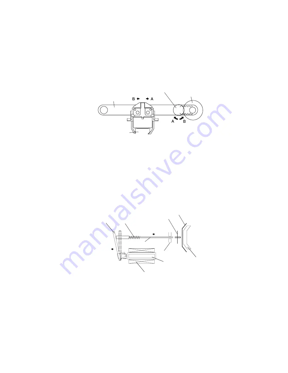
Print head unit movement
When the carriage motor is driven and the carriage motor gear moves in the direction of arrow B
(forward rotation), the rotational power is conveyed to the belt drive pulley, then the belt. Next,
the carriage sub assembly, which is fixed to the belt, moves in the direction of arrow B.
When the carriage motor gear rotates in the direction of arrow A (reverse rotation), the carriage
sub assembly moves in the direction of arrow A.
Wire movement when a single dot is printed
When the specified print head drive pulse is input to the drive coil, the iron core is magnetized,
and the actuating plate is pulled in the direction of arrow A. This action pushes the wire toward
the platen. When the wire strikes the ink ribbon and paper against the platen, a single dot is
printed. (The “platen” is the portion of the paper feed frame being struck by the wires during
printing.)
When energizing of the drive coil is completed, the wire and actuating plate are returned to the
standby position by the wire return spring and actuating plate spring.
Figure 2-3 Print head unit movement
Figure 2-4 Printing
Belt
Carriage motor gear
Belt drive pulley
Carriage sub assembly
B
A
Actuating
Paper roll
Ink ribbon
Wire return
Drive coil
plate
spring
Wire
Wire guide
Iron core
Platen
— 28 —
Содержание UP-250
Страница 1: ...EXTERNAL PRINTER FEB 2000 MODEL UP 250 without price TECHNICAL MANUAL ...
Страница 95: ... 86 END END Yes No Action 4 Replace main PCB Replace printer OK Action 4 mechanism assembly ...
Страница 136: ... 127 ...
Страница 149: ... 140 Main Circuit Board Parts Layout ...
Страница 150: ... 141 RS 232 Serial Interface Circuit Board Parts Layout ...
Страница 151: ... 142 IEEE 1284 Parallel Interface Circuit Board Parts Layout ...
Страница 152: ...RS 485 Serial Interface Circuit Board Parts Layout 143 ...
Страница 159: ... 150 Printer Mechanism Unit Lubrication Points Diagram 1 O 10 2 G 31 6 G 31 7 G 31 5 G 31 7 G 31 8 G 31 ...
Страница 160: ... 151 Case Unit Lubrication Points Diagram 4 G 31 4 G 31 3 G 31 3 G 31 ...
Страница 163: ... 154 EXPLODED DIAGRAM FOR TM U200B U210B NO 1 ...
Страница 164: ... 155 EXPLODED DIAGRAM FOR TM U200B U200PB U210B U210PB NO 2 ...


