


—
— 111
✔
Make sure there is space between the slanting edge of the print head FPC and slanting side
of the carriage sub assembly, and between the FPC edge and portion A. If there is no space,
the print head FPC may not be inserted into the print head unit firmly. Remove the print
head unit and insert the print head FPC again.
Main assembly 14
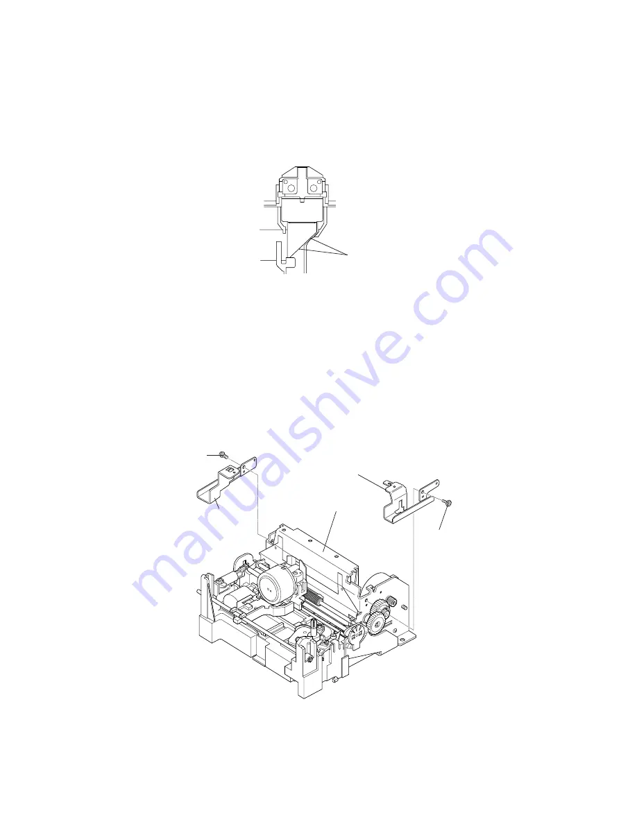
Left cover fixing plate and right cover fixing plate
1. Attach the dowel of the left cover fixing plate into the hole in the paper feed frame, and
secure it with the screw.
2. Attach the dowel of the right cover fixing plate into the hole in the paper feed frame and
secure it with the screw.
There must be space
Right cover fixing plate
Left cover fixing plate
CCS-tite (M3x6)
[0.69 to 0.88 N • m
(7 to 9 kgf • cm)]
CCS-tite (M3x6)
[0.69 to 0.88 N • m
(7 to 9 kgf • cm)]
Paper feed frame
Содержание UP-250
Страница 1: ...EXTERNAL PRINTER FEB 2000 MODEL UP 250 without price TECHNICAL MANUAL ...
Страница 95: ... 86 END END Yes No Action 4 Replace main PCB Replace printer OK Action 4 mechanism assembly ...
Страница 136: ... 127 ...
Страница 149: ... 140 Main Circuit Board Parts Layout ...
Страница 150: ... 141 RS 232 Serial Interface Circuit Board Parts Layout ...
Страница 151: ... 142 IEEE 1284 Parallel Interface Circuit Board Parts Layout ...
Страница 152: ...RS 485 Serial Interface Circuit Board Parts Layout 143 ...
Страница 159: ... 150 Printer Mechanism Unit Lubrication Points Diagram 1 O 10 2 G 31 6 G 31 7 G 31 5 G 31 7 G 31 8 G 31 ...
Страница 160: ... 151 Case Unit Lubrication Points Diagram 4 G 31 4 G 31 3 G 31 3 G 31 ...
Страница 163: ... 154 EXPLODED DIAGRAM FOR TM U200B U210B NO 1 ...
Страница 164: ... 155 EXPLODED DIAGRAM FOR TM U200B U200PB U210B U210PB NO 2 ...


