


- 25 -
5-6. VGA
The QT-8000 has an analog RGB interface connector installed on the rear side. It is able to
connect to an expansion CRT monitor, and the system can display on both the LCD display
and the CRT individually or simultaneously. However, as the LCD display adapted is of the
resolution of 1024 x 768, therefore, to support a CRT monitor simultaneously, the CRT’s
VGA resolution has to be set to 1024 x 768, too. It can also support CRT maximum
resolution of up to 1600 x 1200 with 8bit on Dual-Display Mode colors. Also, an automatic
horizontal frequency detective type CRT is only approved.
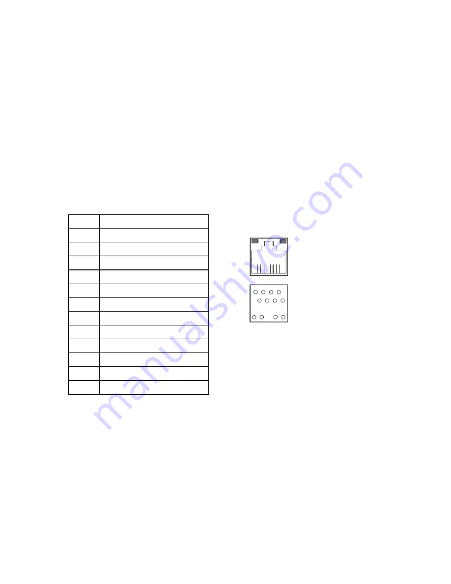
5-7 Ethernet
The QT-8000 provide a high performance Ethernet (RJ-45) interface. For network
connection, just plug in one end of cable of a 10/100-Base-T hub to the standard Ethernet
phone jack. The pin assignment of the RJ-45 is listed below.
PIN
ASSIGNMENT
1
TX+
2
TX-
3
RX+
4
ISOLATED GND
5
ISOLATED GND
6
RX-
7
ISOLATED GND
8
ISOLATED GND
9
LED – SP LED
10
PULL HI
11
LED – LI LED
12
LED – ACT LED
• The green LED detect power link, and the Yellow LED is used to detect data active
transfer signal.
5-8. Keyboard
The QT-8000 provides a standard PS/2 keyboard connector located at the rear side. If the
user would like to use AT keyboard interface, a conversion cable is also provided to make
this connection.
5-9. PS/2 Mouse
The QT-8000 has one PS/2 Mouse connector located at the rear side. A simple plug-in will
make the connection.
Yellow
Green
9
1
1
2
7
8
10
8
12
11
UPT1
Содержание QT-8000
Страница 10: ...8 2 DISASSEMBLY STEP 1 Remove HDD Cover STEP 2 Remove HDD Pull out the HDD cable Release the 4 screws...
Страница 11: ...9 STEP 3 Remove Card Reader Cover STEP 4 Remove Back Cover Release the 3 screws Release the 15 screws...
Страница 12: ...10 STEP 5 Remove Chassis_T STEP 6 Remove CF Board MSR Board Release the 6 screws Release the 5 screws...
Страница 14: ...12 STEP 9 Remove Main Board STEP 10 Main Board Release the 5 copper pillars Release the 4 screws...
Страница 15: ...13 STEP 11 Remove Inverter Board STEP 12 Inverter Board Release the 2 screws...
Страница 16: ...14 STEP 13 Remove the Control Board of Touch Panel STEP 14 Control Board of Touch Panel Release the 2 screws...
Страница 17: ...15 STEP 15 Remove Base STEP 16 Remove LCD Panel Remove 14 screws Remove 4 screws from both side of system base...
Страница 18: ...16 STEP 17 Remove Touch Panel Remove Touch Panel...
Страница 20: ...18 5 6 7 8 9 10...
Страница 57: ...55 7 2 Block diagram 1 System Connection Diagram...
Страница 58: ...56 2 System block diagram...
Страница 62: ...60 5V 4 6 12V 2 4 RI 17 18 5V 7 9 COM3 12V 9 11 RI 19 20 5V 8 10 COM4 12V 10 12...


