IOM-Ranger
13
Sub sec tion C, Articles 1 through 10.
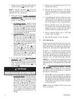
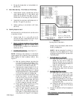
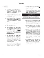
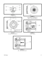
2. Slide retainer sleeve subassembly (8) onto
the stem assembly (7) with the stem retainer
carbon bushing (8.2) end against the stem
(7) subassembly shoulder.
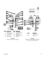
3. Apply lubricant (silicon grease or equiv a lent)
to O-ring (30), and slide backup ring (31) and
O-ring (30), re spec tive ly, into groove on stem
(7) groove-end. See Figure 21 for O-ring (30)
orientation.
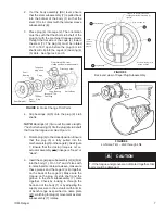
4. Insert the stem/retainer sleeve (7)(8) as sem bly
into the body (1), aligning the hole in the
retainer sleeve (8) to be directly in line with
the thread ed hole in the body (1) bonnet.
Align the stem sub as sem bly (7) so that the
plug’s (6) tongue and the stem's (7) groove
will engage. Insert as sem bly.
NOTE:
A small "flat" area has been milled on the
stem and for correct engagement this "flat" must
be on the same side as the face of the plug (6).
5. Visually confirm alignment of hole in re tain er
sleeve (8.1) with threaded hole in body (1)
bonnet. Insert and tighten stem re tain er screw
(17).
6. Rotate stem (7) to ensure tongue and groove
engagement with plug (6).
7. Proceed to Section IV, Subsection G. for
in stal la tion of packing (13).
J. Pressure
Test:
1. Cashco recommends that a pressure integrity
test be performed following reassembly when
the pack ing set (13) has been replaced.
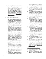
check ing each spacer ring (29) after each
tight en ing. When spacer ring (29) can
no long er be rotated freely by fingers,
make an ad di tion al 1/2 revolution – no
further tight en ing should occur to main tain
the “live-loaded” intent of the design.
Over tight en ing of the design as de scribed
caus es the mechanism to func tion as a
“jammed pack ing. This will de feat the
design intent of the mech a nism and will
increase packing (13) wear.
c. Refer to Actuator Maintenance Man u als
IOM-48 or 148 to reconnect ac tu a tor/arm
housing (AA) to yoke (12).
6. Common to Opt-38J Jammed Packing Only:
NOTE:
Packing follower (15) must penetrate into
the stuffing box of the body (1)
.
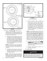
a. Install nuts (22) on packing studs (21) and
finger tighten.
b. Refer to Actuator Maintenance Man u als
IOM-48 or 148 to reconnect ac tu a tor/arm
housing (AA) to yoke (12).
c. Tighten packing nuts (22) to torque levels
indicated in Table 5.
Table 5
Packing Nut Torques
Body Size
Torque
in-lbs.
N-M
1",1-1/2", 2"
(DN25, 40, 50)
50
67
3", 4"
(DN80, 100)
130
176
6" & 8"
(DN150, 200)
165
223
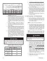
NOTE:
When valve is returned to operation, check
for leakage and tighten the nuts (22) evenly in
alternating 1/4 revolution in cre ments until leak age
stops. DO NOT OVERTIGHTEN.
H. Slurry Trim – Opt-AS:
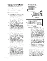
1. Install the trim in the body (1) per Section IV,
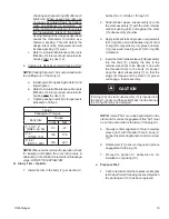
CAUTION
If O-ring (30) on stem subassembly (7) is inserted into
the body (1) cavity and then pulled back into the bonnet,
the O-ring (30) may be damaged.


