9
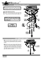
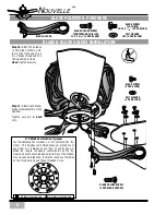
Step 12.
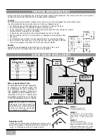
Remove the wire nuts on the BLACK and WHITE
wires from the fan. If necessary remove the insulation
from the last
1
/
2
” of each wire (fan and light fixture).
Step 14.
Attach the switch housing wires to the light
fixture wires by placing the bare ends of the wires to-
gether and then securing with a wire nut. Connect in
this order:
Step 13.
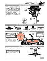
Have an assistant hold up the light fixture
until it is close to the adaptor ring.
• WHITE wire from fan to WHITE wire from
light fixture. Secure with wire nut.
• BLACK wire from fan to BLACK wire from
light fixture. Secure with wire nut.
Inspect each wire nut and ensure that no bare wire is
visible; pull on each wire to test the connection is
mechanically sound.
LIGHT FIXTURE INSTALLATION
LIGHT FIXTURE ELECTRICAL CONNECTIONS
WIRENUT
LIGHT FIXTURE
SCREW
LIGHT FIXTURE HARDWARE
2 BLACK
WIRES
2 WHITE
WIRES
LIGHT
FIXTURE
ADAPTOR
RING
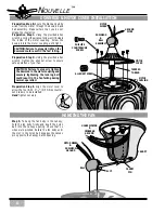
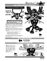
Step 15.
Lift the light fixture
assembly, making sure not to
pinch the wires, and align the
three holes in the side of the
fixture with the three threaded
holes in the adaptor ring and
install the three (3) 6-32 X
5
/
16
″
Phillips screws.
Hand
tighten securely.
LIGHT FIXTURE SCREW
PHILLIPS COUNTERSUNK
6-32 X
5
/
16
″
(3)
N
OUVELLE
™
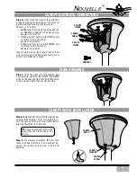
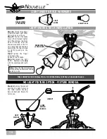
CAUTION: Before installing light fixture check
that the light fixture is securely tightened
to the lower switch housing.
ASSEMBLY
NUT
LIGHT
FIXTURE
LOWER
SWITCH
HOUSING
CHECK THAT THESE
LOCKNUTS AND THE
ASSEMBLY NUT ARE
VERY TIGHT
TIGHTEN WITH A
WRENCH IF REQUIRED
IF NOT INSTALLING LIGHT FIXTURE SKIP TO STEP 19
Содержание Nouvelle
Страница 1: ...NOUVELLE OWNER S MANUAL...

