Casablanca Isotope C30G45H Скачать руководство пользователя страница 13

13

PrIME

•TOUCH

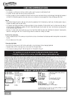
® W-505 CONTrOl INSTallaTION

CONTrOl BraCKET INSTallaTION
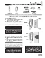
haRdWaRe 

(not to scale)

P

RIME•

T

OUCH

®

SAFETY FIRST: To reduce the risk of electrical shock, this fan must be installed 

with an isolating wall control/switch. CAUTION! Do not use with wall dimmer. 

Standard toggle Light Switch

a.   Remove the two screws holding the switch cover 

  plate. do not remove the cover plate.

b.   Orient the control bracket as shown and line up 

  the  two  inner  mounting  holes  with  those  on  the 
  switch.

c.   insert  screws  and  tighten  using  the  provided 

  screwdriver.


Wall installation

a.   locate a 2 x 4 wall stud in a convenient location.

b.   Orient the control bracket as shown over the 2x4 

  stud.

c.   use the one-inch wood screws in the inner mounting 

  holes.  insert  and  tighten  the  screws  using  the 
  provided screwdriver.

nOTe:  The wall anchors and 6-32 x 1" screws may 
be used in situations where mounting to a stud is not 
possible. use the inner mounting holes. after securing 
the anchor, discard the anchor’s pointed screws and 
use the supplied 6-32 decor ovalhead screws. 

WaRning! 

to  reduce  the  risk  of  fire  or 

electric shock, do not use this fan with any 
solid  state  speed  control  device.  use  only 
the control provided with this fan.

Caution! do not use with wall dimmer or 
rocker switch.

this  device  complies  with  RSS-210  of 
industry Canada. operation is subject to the 
following two conditions: (1) this device may 
not  cause  interference,  and  (2)  this  device 
must  accept  any  interference,  including 
interference  that  may  cause  undesired 
operation of the device.

NOTICE:    Changes  or  modifications  not 

expressly approved in writing by Casablanca 
Fan Company may void the user’s authority 
to operate this equipment.

MountinG 

hoLeS

MountinG 

hoLeS

ContRoL 
BRaCKet

ContRoL 
BRaCKet

StandaRd 

toGGLe 

SWitCh

SWitCh 

CoveR 

PLate

SCReWS,

6-32 X 1"(2)

Wood SCReWS,

1" (2)

dRYWaLL anChoRS,

6-32 (2)

12v BatteRY

W-505

ContRoL 

(tRanSMitteR)

W-505 

ContRoL 
BRaCKet

SCReWS,

6-32 X 

3

/8" (2)

Содержание Isotope C30G45H

Страница 1: ...x before attempting any installation procedure Isotope Owner s Manual Read and Save These Instructions CONTENTS PN C3543001 AT0309 Parts guide 3 Introduction 4 Before You Start 4 Safe Use 4 MOUNTING R...

Страница 2: ...packaging materials be certain that all parts have been removed Use a clean dry paintbrush to remove small Styrofoam pieces that may remain after unpacking Do not brush Styrofoam into wiring cavities...

Страница 3: ...8 32 Roundhead screws and Washers 2 EA 5 Screw Pack A 11 2 Wood Screws and Washers 2 EA 6 Screw Pack A 3 Wood Screws and Washers 2 EA 7 Screw Pack A Wire Nuts 3 8 Screw Pack B Fan Mounting Screws 4 9...

Страница 4: ...res are within the canopy and that no wires are being pinched WARNING Do not bend the blade brackets when installing the brackets balancing the blades or cleaning the fan Do not insert foreign objects...

Страница 5: ...r open cupboard doors to clear the fan blades Do not install a fan close to or over a pool or spa High humidity combined with corrosive gases will destroy the finish and warp the blades Fan Size Varia...

Страница 6: ...ed Step 1a Carefully feed the ceiling wires through the center hole of the ceiling mounting plate Attach the plate as shown with ground wire down to the ceiling fixture outlet box with the screws prov...

Страница 7: ...the fan on the hook of the ceiling mounting plate This will help you in making the electrical connections as shown in Figure 2 and Figure 3 Step 2a Unlock the canopy cover from the canopy ring tabs t...

Страница 8: ...s shown in Figure 4 BLACK wire from fan to the BLACK conductor wire from the power source Secure with wire nut as shown in Figure 4 3 GREEN GROUND WIRES 2 WHITE WIRES 2 BLACK WIRES Figure 4 Figure 5 S...

Страница 9: ...ed slots as shown in Figure 7 Step 2g Install the other two fan mounting screws by holding the fan body cover to the ceiling mounting plate as shown in Figure 8 Tighten all four screws until hand tigh...

Страница 10: ...nopy ring Lock the CANOPY RING TABS and the CANOPY TAB HOLDERS by rotating the canopy cover clockwise as shown in Figure 11 locking the canopy ring in to place CANOPY RING Step 2j Check your work by m...

Страница 11: ...ot located on the blade ring Make sure that the Casablanca Logo is facing downward Using three blade screws and washers attach the blade to the blade ring as shown in Figure 2 Install three screws and...

Страница 12: ...bulb by the plastic sleeve to screw it into the socket GLASS SHADE Figure 1 Figure 2 Glass Installation Step 5a Align the glass shade up with the bottom of the fan as shown in Figure 2 and locate the...

Страница 13: ...where mounting to a stud is not possible Use the inner mounting holes After securing the anchor discard the anchor s pointed screws and use the supplied 6 32 decor ovalhead screws warning To reduce th...

Страница 14: ...to 1000 Low Med High Light Reverse fan off Note You may want to label your remote controls to assure you do not mix them up warning Do not turn the power off at the circuit breaker then back on for a...

Страница 15: ...ate assembly Make sure the wire nuts inside the canopy and switch housing are not touching the metal parts and that they have not fallen off the wire splices Tighten as necessary Tighten the blade hol...

Страница 16: ...rence including interference that may cause undesired operation of the device 1 This device complies with part 15 of the FCC Rules Operation is subject to the following two conditions 1 this device ma...

Отзывы: